4.10.1.1 Create a new HVAC System(s) for the Design model
This step in the navigator will open the “HVAC System Design Wizard.” The HVAC System Design Wizard is a simple step by step approach to select and size HVAC system(s). The HVAC System Navigator has four steps; these steps have been explained below:
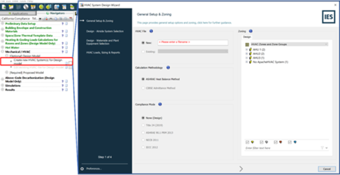
Step 1 of 4: General Setup & Zoning section
In this step, the user needs to have a general setup of the system.
· Name the HVAC design System
· The Load Calculation methodology is set to “ASHRAE Heat Balance Method” by default
· Zone the spaces (if not done already) in the model to represent the HVAC zones in the design model.
HVAC System Design Wizard Step 1 of 4
Further details about the General Setup & Zoning section of the HVAC System Design Wizard can be found in the User Guide.
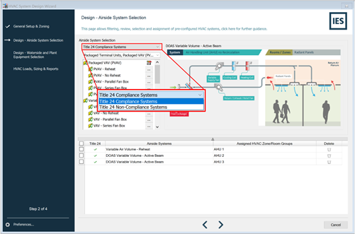
Step 2 of 4: Design – Airside System Selection
In this next step of HVAC System Design Wizard, the user needs to select the Airside Systems for the HVAC System zones.
· Users can select from a large number of pre-defined HVAC systems. For the design Model, the system can be either a “Title 24 Compliance Systems” or “Title 24 Non-Compliance Systems.” Note that if the user selects a “Title 24 Compliance Systems,” then the design HVAC system can be imported as a proposed HVAC system in the next step of the navigator (Section 4.8.2.2).
HVAC System Design Wizard Step 2 of 4: Title 24 Compliance Non-Compliance System selection
· Airside System selection drop-down list can reduce the amount of HVAC Airside Systems to make selection easier
· When any single system has selected the graphics on the right-hand side of the display updates with information of the chosen HVAC system.
· The selection of an Airside system can be made by clicking on the ‘…’ box next to the HVAC System and then choose the HVAC Zone for that system.
HVAC System Design Wizard Step 2 of 4
Further details about the Design – Airside System Selection section of the HVAC System Design Wizard can be found in the User Guide.
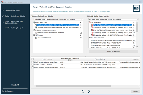
Step 3 of 4: Design – Waterside and Plant Equipment Selection
In this step, the user will select the waterside and plant equipment for the HVAC System. Initially, default equipment is assigned to the system. However, the user has the option to edit them as needed.
· Similar to the Airside selection step, the number of Waterside system chosen is shown with both number and in the list of systems. The automatic selection shows the primary and, where appropriate, the secondary Heating and Cooling Waterside systems per Airside systems.
· If the user wants to choose a non-default system, they can click to the right of the waterside system, which will allow them to select the systems from the drop-down list in the table below.
HVAC System Design Wizard Step 3 of 4
Further details about the Design – Airside System Selection section of the HVAC System Design Wizard can be found in the User Guide.
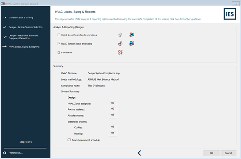
Step 4 of 4: Design – HVAC Loads, Sizing & Reports
User can run the HVAC Zone/Room loads/sizing calculations, HVAC System loads/sizing calculations and Energy Simulations directly from this step.
If the user does not intend to make any further changes to the HVAC system then they can follow the following steps:
· Check box next to the simulation(s) you want to run in the “Analysis & Reporting (Design)”
· Check the “Export equipment schedule” under “Summary” to get the summary of the HVAC systems and their assignment.
· After you click “OK” the HVAC files will be created and populated, the engine starts sizing calculations and autosizes the systems and generates reports.
HVAC System Design Wizard Step 4 of 4
Further details about the Design – Airside System Selection section of the HVAC System Design Wizard can be found in the User Guide.