3.1.2.2. Illuminance Menu
File Menu
The Illuminance File menu options are the same ones available in the luminance File menu. Please refer to the Luminance Menu section.
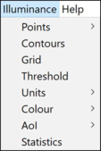
Illuminance Menu
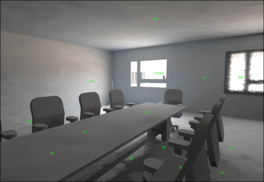
Points
There are three sub-options in this menu: Load, Save and Clear
· Load: Will load a previous point positions file that contains the lux/DF point positions previously saved.
· Save: Saves the currently defined point positions in the image, which can then be read in later using the Load option above.
· Clear: Clears the current points from the image.
Contours
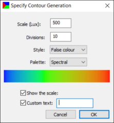
This option allows the creation of a separate image of illuminance contours (lux or DF). This will be created as a separate image (.pic file)
· Scale: Choose the maximum value to be displayed
· Divisions: Set the number of divisions from zero to the maximum value. For example, if the scale (Lux) =1000, then 10 divisions will result in 10 contour bands of 950, 850, 750 Lux etc, down to 50 Lux.
· Style: Select the preferred style of contour (false colour, contour lines or contour bands).
· Palette: Select from a range of contour colour styles.
· Show the scale: Enable or disable the scale text in the image
· Custom text: Add additional text to the image
Clicking OK will create and open the contour image:
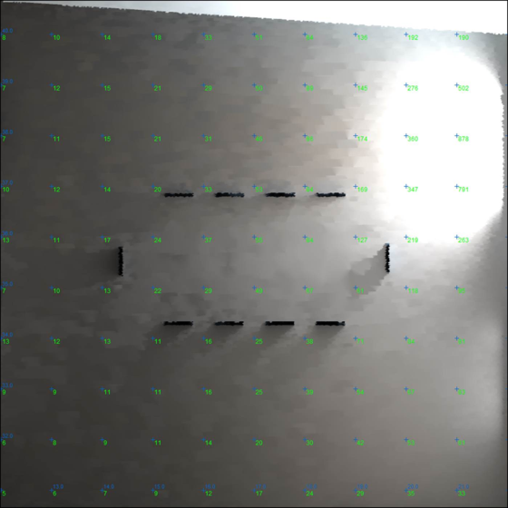
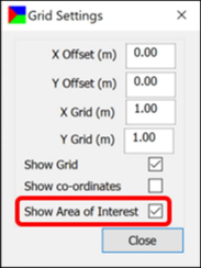
Grid
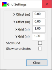
This opens the same dialogue box as the Grid settings button in the toolbar. This alters the grid of lux/DF values in an image. This is applicable for a plan view image only. Specify the size of the grid and the offset in both axes. Tick the checkbox labelled Show Grid to see the point values (in the selected units) at the specified intervals. If the Show co-ordinates checkbox is ticked, the x and y coordinate system will be shown on the image.
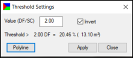
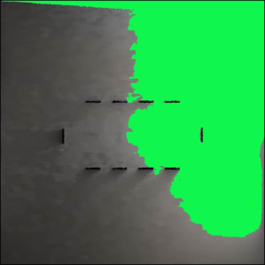
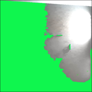
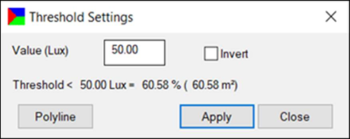
Threshold
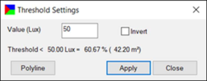
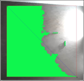
This will display the area in a plan view image where the DF or lux level is above or below a specified value. This option is only available for plan view images.
The dialogue has an input box to set the threshold value based on the unit selected in Units.
When the Invert checkbox is ticked, the area above the threshold value will be highlighted.
When Invert is unticked, the area below the threshold value will be highlighted.
In both cases, the area of the highlighted region and its percentage of the total area will be displayed in the dialogue.
The Polyline option can be used to save the threshold outline as a DXF drawing format file.
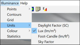
Units
Defines the units in which the results are displayed:
Daylight Factor and Sky Factor are only available for Standard CIE overcast sky illuminance images.
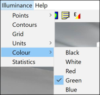
Colour
The font colour for the point values on the image can be changed by selecting the desired colour from the sub-menu:
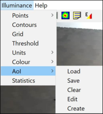
AOI
This option is available only for plan-view images. It is used to show or hide the area of interest (AOI). The area of interest enables analysis of a specific section of the image, omitting the part of the image that is not of interest.
· Load: Is used to load previously saved .aoi files. The selected file should have dimensions within the opened image’s limits, or a warning message will be generated.
· Save: Will save the current AOI.
· Clear: Will clear the current AOI.
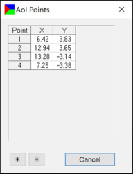
· Edit: Allows editing of the current AOI’s coordinates:
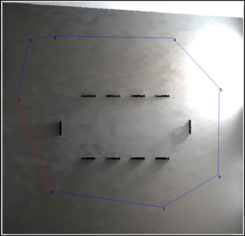
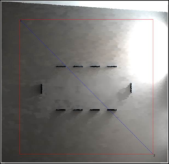
· Create: Will create an AOI in the current plan-view illuminance image. This can be done by left-clicking to define the corners of the AOI. The AOI can be defined either by two points to represent an orthogonal box or by more points to create a general polygon.
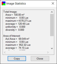
Statistics
Displays a window showing various statistics such as minimum, maximum and average Lux etc, for the whole image or for the AOI. It can be copied to the clipboard and pasted for reporting and analysis purposes.
Note: the outline of the AOI can be made visible or not by enabling the Show Area of Interest check box in the Grid Settings window. The AOI should be drawn first in order for this option to appear in the Grid Settings window.
If the AOI is displayed, when a Threshold image is generated by clicking on the Threshold button in the illuminance toolbar or menu, it will be applied only to the AOI: