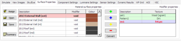
This tab is broken down into two sections:
· Material Surface Properties
· Modifier Properties
Material Surface Properties
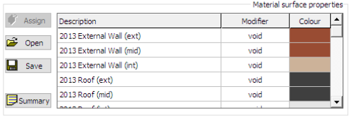
This allows the user to edit the properties pertaining to the materials that are defined in the model. The “Open” and “Save” buttons will save and retrieve this data from a “map” file (the “Assign” button is defined below).
This section shows a scrollable list of the defined materials and the properties that are assigned to each surface. The list will consist of materials defined in assigned opaque and glazed constructions, and materials representing components.
Construction Materials
The construction that is assigned to a surface or opening determines the material(s) that are used in Radiance simulations for that surface or opening. Each of these materials can have different properties and a different surface modifier defined for it. The exact surfaces available varies depending on construction type:
The following construction types define three materials – the external surface (labelled “(ext)”), the mid-layer (labelled “(mid)”) and the internal surface (labelled “(int)”):
- External Wall
- TSC Wall
- Ground/Exposed Floor
- Roof
- Active Thermal Roof
The following construction types also define three materials – the ceiling surface (labelled “(ceiling)”), the mid-layer (labelled “(mid)”) and the floor surface (labelled “(floor)”):
- Internal Ceiling/Floor
- Active Thermal Ceiling/Floor
The following construction type defines two materials – the partition surface (no sub-label in the list) and the mid-layer (labelled “(mid)”):
- Internal Partition
The following construction type defines two materials – the glazed surface (no sub-label in the list) and the frame (labelled “(frame)”):
- Internal Window
The following construction types define three materials – the glazed surface (no sub-label in the list), the frame (labelled “(frame)”) and the glazed surface with the effect of a blind (used for sDA simulations, labelled “(blind)”):
- External Window
- Roof Light
All other construction types define a single material, with no sub-label in the list.
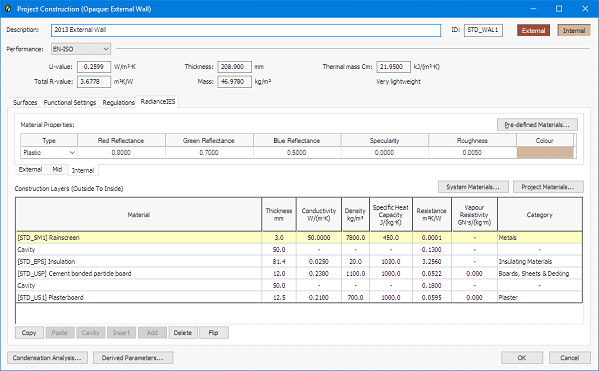
To edit a construction material, double-click on the material description. This will open the construction containing the material for edit, with the RadianceIES tab active and the properties for the selected material displayed. For example, double-clicking on 2013 External Wall (int) would display the following:
Where the construction type defines more than one material (as in the above example), sub-tabs are used within the main RadianceIES tab to access the different materials. Note that you can edit any of the construction’s properties here – not just those relating to the Radiance material(s). However, the Radiance material properties are displayed by default for convenience.
The Radiance material properties are displayed using a grid:
The columns displayed are dependent upon the Type selected for the material. The following types are defined:
- Plastic: This type is used to represent any non-metallic opaque material. It is not available on the Glazed Surface and Glazed Surface w/ Blind (sDA) materials used in External Window and Roof Light constructions.
- Metal: This type is used to represent any metallic opaque material. It is not available on the Glazed Surface and Glazed Surface w/ Blind (sDA) materials used in External Window and Roof Light constructions.
- Glass: This type is used to represent a standard glass material. It is only available on the materials defined in glazed constructions and on the material defined for a door construction.
- Di-electric: This type is used to represent a glazed material with di-electric properties. It is only available on the materials defined in glazed constructions and on the material defined for a door construction.
- Translucent: This type is used to represent any other type of translucent glazed material. It is only available on the materials defined in glazed constructions and on the material defined for a door construction.
The following columns will be displayed when Plastic or Metal is selected as the Type:
- Red, Green and Blue Reflectance
- Reflectance (read-only, derived from other values)
- Specularity
- Roughness
The following columns will be displayed when Glass is selected as the Type:
- Red, Green and Blue Transmissivity
The following columns will be displayed when Di-electric is selected as the Type:
- Red, Green and Blue Transmissivity
- Refractive Index
- Hartmann Constant
The following columns will be displayed when Translucent is selected as the Type:
- Red, Green and Blue Reflectance
- Specularity
- Roughness
- Transmissivity
- Transmitted Specularity
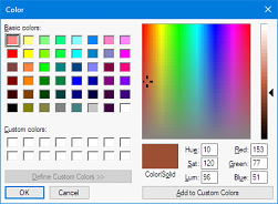
In all cases, the final column is Colour. In Glass, Di-electric and Translucent types, this will display Clear if the red, green and blue values are identical – in all other situations, and for Plastic and Metal types, it will display a colour block representing the colour as defined by the red, green and blue values. When double-clicked, a colour picker is displayed to allow the red, green and blue values to be selected visually (note that the colour picker displays values between 0-255, whilst the Radiance material references a colour as a factor between 0.0-1.0):
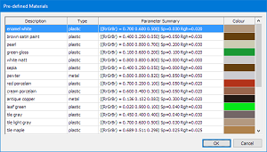
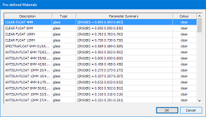
A set of pre-defined material properties is provided for convenience – this can be accessed by clicking the Pre-defined Materials… button above the grid. The available pre-defined materials will depend on the Type currently set on the material:
These show predefined materials for opaque types on the left, and for glazed types on the right. In both cases, selecting a material and clicking OK (or double-clicking on a material) will apply that pre-defined material’s values to the current material.
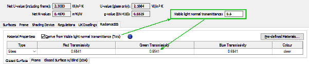
In the Glazed Surface material for glazed constructions, an additional checkbox is displayed above the grid, labelled Derive from Visible light normal transmittance (Tvis). When this option is checked, the type is automatically set to Glass with the RGB transmissivity values each set to a value calculated from the construction’s current Visible light normal transmittance value. The grid is disabled when this option is checked, and changing the Tvis value will automatically update the RGB transmissivity values appropriately.
Note that this option only affects the Glazed Surface material – it has no effect on either the Frame material (all glazed constructions) or Glazed Surface w/ Blind (sDA) material (External Window and Roof Light constructions). If a pre-defined material is selected via the Pre-defined Materials list (see above), this option is automatically turned off.
Component Materials
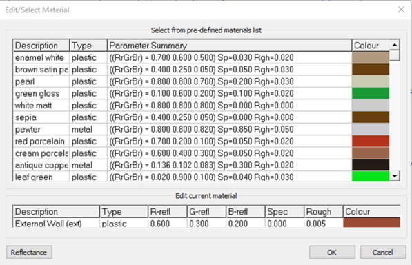
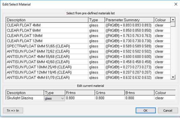
To view or edit a component material, double-click on the material name, the following dialog box opens.
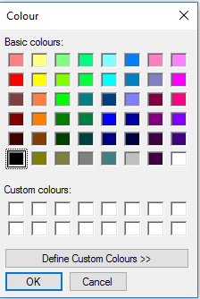
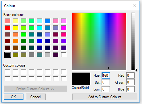
From this dialog box you can select from the list of materials or manually adjust the RGB values. The “Type” can be either “plastic” or “metal”. These both have the same set of parameters. If the “Colour” field is double-clicked then the following is displayed –
If the “Define Custom Colours” button is pressed then the window expands to the following –
Note: in Radiance colours are defined by RGB values in the range 0.0 - 1.0 and the window above uses the integer range 0 - 255.
If a glass material is selected a different set of pre-defined materials is displayed.
The “Type” has a choice of three possible options - “glass”, “trans” or “dielectric”. These all have different parameters.
Calculating Reflectance
For solid materials (plastic and metal) the “Edit/Select Material” pop-up window has a “Reflectance” button, clicking this will calculate and display the reflectance value –
Calculating Transmissivity
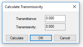
If the user has a transmittance value and wishes to know the transmissivity value of this, then they can simply click the button labelled “Tn => tn”, which displays the “Calculate Transmissivity” dialog box below –
The user enters their value in the “Transmittance” field and then clicks the “Calculate” button. The resultant transmissivity value will now be displayed in the “Transmissivity” field. Should the user wish to use this value for the selected glazed surface, then click “OK” and the R-trns, G-trns and B-trns fields in the grid will be updated to reflect this.
This calculation is identical to that used for Calculate Transmissivity in CDB for construction materials.
Assigning Constructions
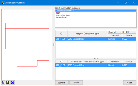
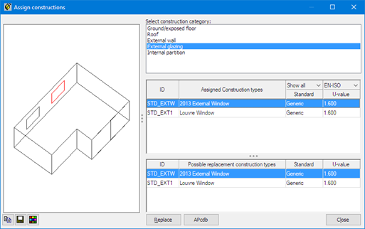
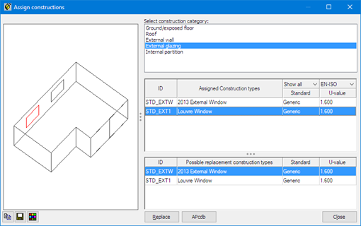
The “Assign” button is used to change the assignment of constructions (and therefore, surface material properties) for selected objects –
The required “Construction Category” is selected in the top list, with the available constructions that are currently assigned shown in the middle list and highlighted in red in the preview on the left. The user then picks the replacement construction to assign to the highlighted surfaces/openings. The “Replace” button will make the required change. The “APcdb” button can be used to open the construction database to edit existing constructions, or to create new constructions. Note that the construction database can also be accessed using the

button on the main toolbar.
Modifier Properties
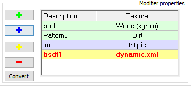
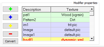
This allows the user to create/delete/edit the parameter definitions for patterns, images and BSDF.
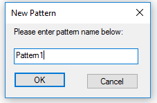
Click the green “+” button to add a new pattern, enter pattern name (this name cannot contain spaces).
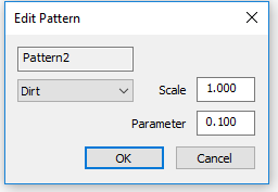
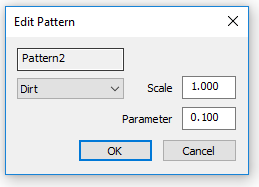
When “OK” is clicked the Edit Pattern dialog pops up where the pattern properties can be adjusted and the pattern is added to the grid.
Once a pattern has been added, the user can then assign this pattern to the modifier field of a surface.
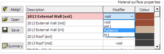
To assign a pattern to a given surface material, the user should select the material from the list provided (Material surface properties) and double click the “Modifier” field. They will now see a drop down list of all available patterns in the project. Simply select the pattern you wish to apply to that selected material.
The “-” button will delete the selected Modifier and any materials which reference this pattern will revert to the “void” modifier.
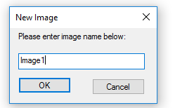
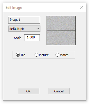
The blue “+” button works exactly as for patterns – creating images. Enter image name and click ok.
To edit the other parameters the following window is displayed when the selected item is double clicked -
BSDF stands for bidirectional scattering distribution function.
Essentially, it is a mathematical function that determines the probability that a specific ray of light will be reflected (scattered) at a given angle. In short, the BSDF means that the light coming through the glass or shade will be scattered. The type of glass or shade determines the distribution function, which in turn determines how the light is scattered and how the material appears.
There are two ways of using a BSDF in the VE and it depends on what the BSDF is meant to model - if the BSDF represents a glazing system then it can be applied to a glass material (Scenario 1), if it represents a blind or other device it can be applied to a component that the user has created (Scenario 2).
Note: it is up to the User to provide their own BSDF data file (xml).
BSDF modifiers can only be used for glass materials.
Scenario 1: modify glazing to use a BSDF material
Go into the "Surface Properties" tab.
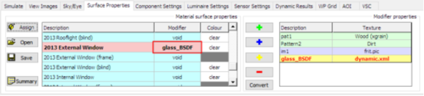
Create a new BSDF property (using the yellow "+" button).
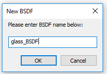
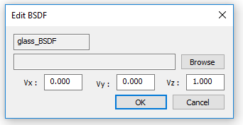
After entering name, "Edit BSDF" dialog opens.
Use the "Browse" button to find the "xml" file that defines the BSDF.
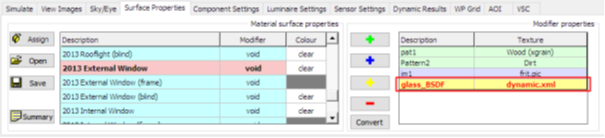
The BSDF description is now loaded.
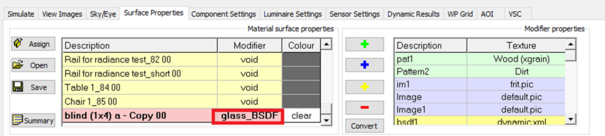
This can now be applied to a glazed surface material by changing the "Modifier".
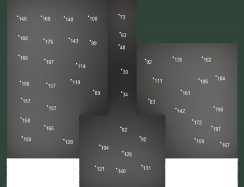
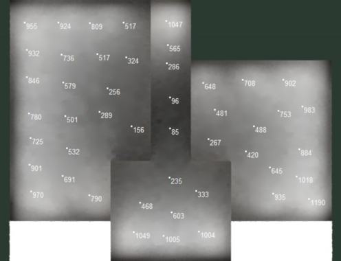
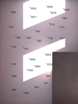
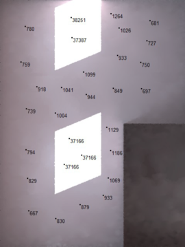
When we now perform a simulation the BSDF definition will be substituted for all uses of the "2013 External Window" glazed surface material - here's a simulation for the ground floor of the test model:
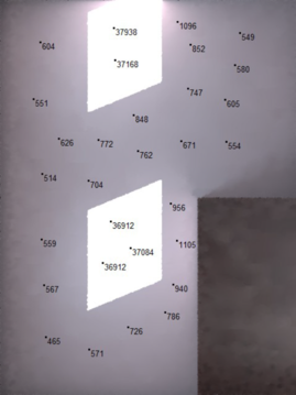
Compared with the "default" image (without the BSDF):
If required, create an alternative construction using the construction database and assign it appropriately using the "Assign" option. For example, in this zone we have two windows with different glazing
In this example we would assign the BSDF to "Louvre Window" and not to "2013 External Window" - i.e. the "2013 External Window" modifier would be "void" and the "Louvre Window" modifier would be set to "glass_BSDF".
Scenario 2 : Component to represent a blind added to one of the zones.
In this scenario we have to edit the material property for the Component
Note: the "modifier" can only see the BSDFs when the material property is set to "glass". Also note that the components have to be switched ON (in "Component Settings" tab).
When used in this mode the properties for the component are substituted for the BSDF, so it is irrelevant what properties are defined.
"Default" image with no blind
Image with solid blind image with BSDF blind
The images look similar but the lux levels at back of room are higher for the BSDF blind.