Components Settings
Components are created using the Component Modeller and assigned to zones in ModelIT (see the documentation on these modules for more information).
The “Use Components” switch is used to activate the use of components. The options available in the “Switching” allow for quick selection of default scenarios e.g. all components OFF, only components in a selected room ON.
A list of all components placed in the model will be displayed and you can choose to switch all, none or some of them on.
Individual components can be switched ON or OFF using the button to the left of each component description. The components are also drawn in the canvas window if the user has gone down to the “Component” option at the “Surface” level of decomposition for the selected zone. The “Summary” button generates a window detailing what components are defined in the model and the status of each
Luminaire Settings Tab
Luminaire properties are defined using the LightPro application.
The “Use Luminaires?” switch is used to activate the use of luminaires; the “Daylight off?” switch is then available. The options available in the “Switching” allow for quick selection of default scenarios e.g. all lights ON, only lights in a selected room ON.
When a zone with lights is selected, the list is updated:
Individual lights can be switched ON or OFF using the button to the left of each luminaire description. The luminaire positions are also drawn in the canvas window. The “Summary” button generates a window detailing what luminaires are defined in the model and the status of each.
By default all lights are OFF until they are switched on.
Sensor Settings Tab
Sensor Positions
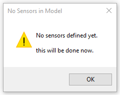
When “Use Sensors” option is ticked on for the first time the sensors are created - a warning message pops up.
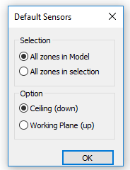
When you click OK you can choose where the sensors are placed (all zones in the model or selected zones only) and their position (ceiling pointing down or working plane pointing up)
To position a sensor manually after default sensors have been placed, select the zone and go down one Level of Decomposition to Room Level, then a Double-Right mouse click in a position where you want to move a sensor to and select “Set Sensor Position”.
In plan view set the x,y-position of the sensor then in any vertical view set the z-position. You can also set the sensor position by typing in the X, Y and Z position in the table.
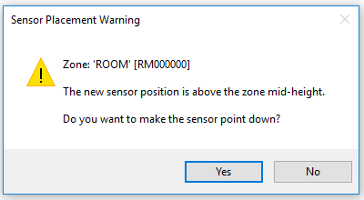
If a sensor is moved above the mid height of the room, a dialog will appear giving the option to make the sensor point downwards.
Note: If a sensor is placed outside a zone then a warning message will pop up. This is allowed for recording the external light levels for reference in formula profiles.
These sensors can be switched ON or OFF as required by selecting each zone individually and choosing ON or OFF in the switching section.
Sensor settings can be saved using the "Save Sensors" button and reloaded using "Read Sensors".
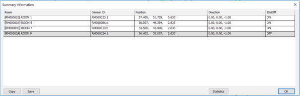
The Summary button will give a grid showing current sensor settings:
Sensors that have been switched off are highlighted grey.
Sensor Outputs
Radiance will perform simulations to determine illuminance at the sensor for given conditions – after setting up the sensors in Sensor Settings tab the simulation is run from the Simulate tab.
In the Simulate tabThe "Apache" default option will produce a model.ill file for use in the ApacheSim Radiance link.
The "Radiance dynamic" button will produce the rad.ril file for use by radiance.
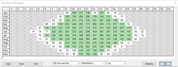
The "Read Illum" button will read the illuminance file (rad.ril) and display the results in a table.
The “Copy” and “Text” buttons will copy the grid image or grid text to the clipboard. The data can then be pasted in to a report or spreadsheet for further edit.
Illuminance values over certain thresholds are highlighted as below:
|
|
white
|
green
|
Red
|
|
Lux
|
< 100
|
100-2000
|
> 2000
|
|
Foot-Candles
|
< 10
|
10-200
|
> 200
|
Units can be changed between Lux and Foot-Candles. Statistics will also be output in the selected units.