Inserting a Passivent Roof Ventilation Terminal (without low level inlets) into a Room
With the appropriate components imported to the project and component properties set (see previous section for details), the components are ready to be assigned to room(s) in your model.
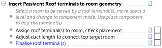
Fig 10: Inserting a component navigator
The Passivent Roof Terminals Navigator guides you through the process:
1. Make sure you are in ModeliT.
2. Select the target room in the view.
3. Use the down arrow to move down one level.
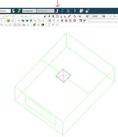
4. Change display mode to component.
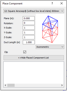
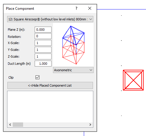
5. The place component dialog will be displayed.
6. Use the combo-box to select the required component.
7. Revise the duct length parameter to suit the target placement.
8. Make sure the view is in a 2D view mode e.g. plan mode.
9. The component will now appear at the cursor and can be placed in the selected plane; left click fix the position.
10. A message may appear; The component is NOT ABOVE. This means that the component is not positioned correctly vertically (as we have only located it in the plan view); press OK and close the dialog.
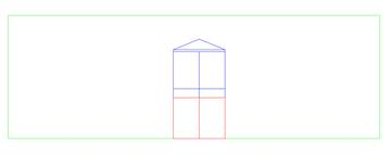
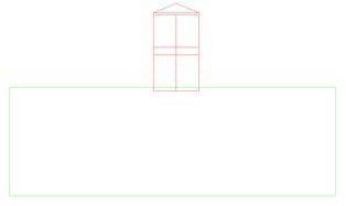
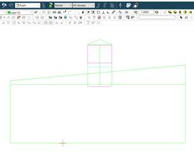
11. Change the view mode to front or right or left view. We can see the component is at room floor level so we need to move it upwards.
12. Pick the whole component by using drag select.
13. Make sure locks are set appropriately (model end point, grid lock etc.)
14. Click on the Move selection set tool.
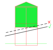
15. Pick a point on the selection set and select-drag the terminal to the room ceiling so that the bottom of the terminal just overlaps into the room.
Ensure that the upper part of the roof terminal (shown in green) does not overlap with any objects or the finalisation process will not work correctly.
16. In the views check you are satisfied with the terminal position in all planes.
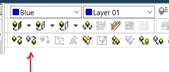
17. Press the Finalize component tool.
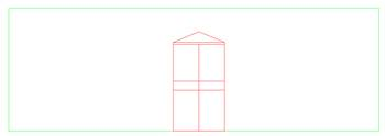
18. The VE now cuts or fixes the component into the model geometry. You will notice that target surfaces and any surfaces in spaces through which the component passes are split in two; this ensures ‘island’ surfaces are not created.
19. Move back up one level.
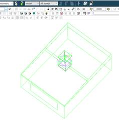
20. The component is now inserted into the model. In this example it is cut through the roof void space above the room. This example demonstrates the need to adjust the duct length parameter.
The components can also be utilised with room windows & louvres if required; however the user will need to set the Macroflo profiles up manually and ensure the set points are synchronized with the room heating/cooling profiles and Roof terminal control profiles. Roof terminal (without low level inlets) fixed values are:
- Plant operation 06:00 – 18:00 weekdays.
- Winter mode To < 12oC.
- Summer mode To > 18oC.
- Heating setpoint 22oC.
- Summer night cooling setpoint 16oC.
- Summer night cool operation 19:00 – 04:00 weekdays.
- CO2 setpoint 1200 – 1700 PPM.