Toolbar Options
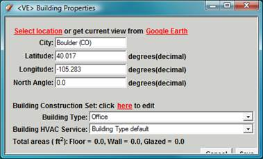
Set Building Properties
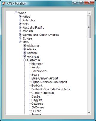
Location is important for building performance analysis because location and climate dictate the performance of the building. Set the location by clicking Select Location from the dialog. This opens the <VE> Location Browser:
The <VE> Location browser allows you to choose major cities throughout the world. The browser has three levels: Continent [Africa, Antarctica, Asia etc]; Country / State / Territory [UK, Arizona, Manitoba etc]; then City [London, Phoenix, Winnipeg etc]. Select a location closest to your project. The local carbon fuel mix and weather data is derived by selecting the location. The resource fuel mix translates into the carbon emissions factor per fuel type for the project that is used to determine the carbon footprint.
Once the location is selected, the latitude and longitude will be updated automatically, if you would like a more exact latitude and longitude, you can use
Google Earth (It will be explained later in the guide).
Within the Set Building Properties dialog, you will also need to set the Building’s Constructions, Building Type and Building HVAC Service.
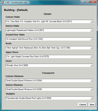
Building Constructions
Constructions: What constructions are used in your building? What glazing types do you wish to use?
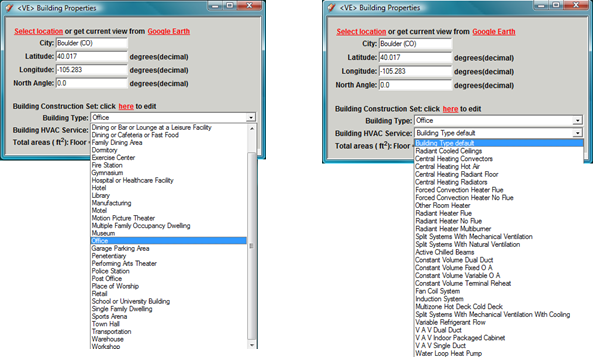
Building Type: What is the principle function of the building you are designing?
HVAC Service: How is you building heated and cooled?
Building Type HVAC Service
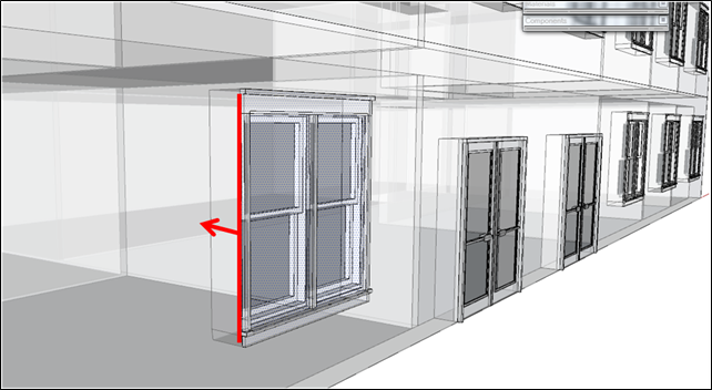
Push Through Doors & Windows (SketchUP Pro thick Walls only)
When a model has been constructed in Thick Walls mode windows and doors can be added as Groups or Components. Ensure the Group/Component has the correct category definition using the IESVE Toolbar Select Groups or Select Components button to define them (see later) then place the Groups/Components on the outer surface of walls.
With the Window or Door Group/Component selected then select the Push Through button and the Group/Component will be pushed through to the inner surface of the wall and will be correctly recognised by the plug-in when rooms are identified.
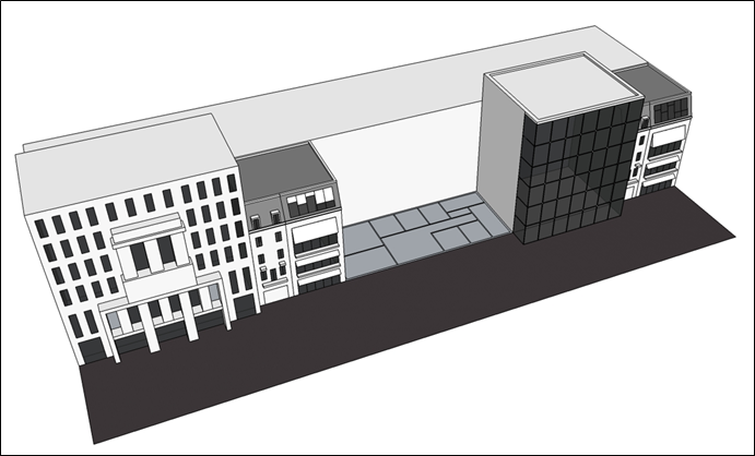
Build a Storey from a Floor Plan (SketchUp Pro Thick Walls only)
Use the Build a Storey tool to extrude any 2-dimensional floor plan (for example a DXF floor plan) into a full height 3-dimensional Thick Walls model.
Step 1
Start with a 2-D floor plan (this can be a dxf, dwg or simply a 2-D sketch).
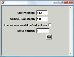
Step 2
Select the floor plan then click the Build a Storey from a Floor Plan button on the IESVE Toolbar. The Build a Storey settings dialog will be displayed.
Enter the Height of each Storey, the Ceiling/Slab Thickness and Number of Storeys then click Go.
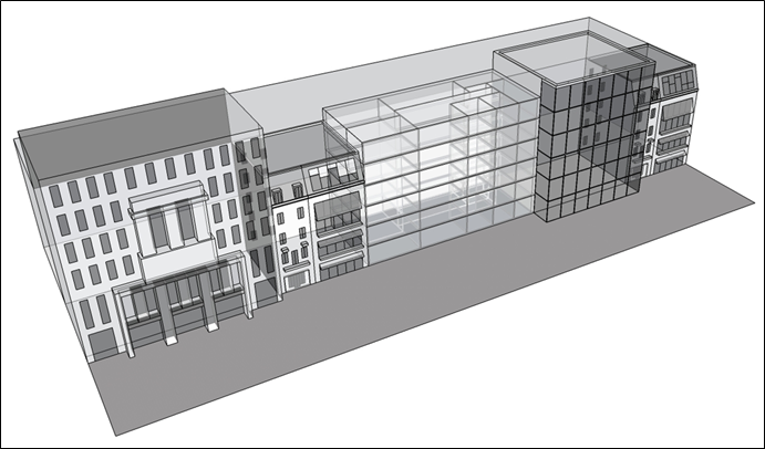
Step 3
The building will be extruded as defined by the settings.
Each Storey has room layout as specified in the original floor plan and the number of storeys, storey height and slab thickness (thick walls) are as defined in the settings dialog.
Note: the user settings dialog has an option to use the current settings as default, tick this to use these values as default the next time the Build a Storey tool is used.
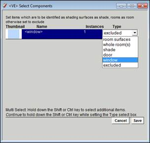
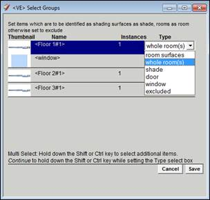
Select Groups
When you have components or groups in your model, you need to go into the ‘Select Components’ or ‘Select Groups’. You need to identify if the specific group(s) or component(s) will be analyzed as room surfaces, whole rooms, shade, door, window, or excluded.
Room: Surfaces defined as room will form part of room boundaries. Rooms define the analysis model that is exported to <VE>.
Room surfaces is used when the Group contains surfaces that form only part of a room shell.
Whole room(s) is used when the Group contains all the surfaces that bound the room (or set of rooms).
It is advised to use whole room(s) wherever possible when modelling to achieve the best results when using the IESVE plug-in for SketchUp. This will allow rooms to be quickly found by the plug-in and gives the best quality geometry export to <VE>.
Shade: Objects defined as Shade are treated as shading surfaces within the model and therefore taken into account for shading analysis, not for thermal analysis.
Door: Group or component will be translated as a door in the <VE> analysis model.
Window: Group or component will be translated as a window in the <VE> analysis model. Note that the group or component will need to have a material opacity between 1-99 in order to translate as window in VE-Pro.
Excluded: All Groups and Components are per default excluded from export and will not appear within the analysis model.
Note: Groups/Components defined as Door or Window can be placed on Thick Walls buildings using the Push Through tool (as described in previous section).