Tabbed Sections, Interface, Links and Workflow
Tabbed sections for System Parameters and Zones Tabular Edit dialogs
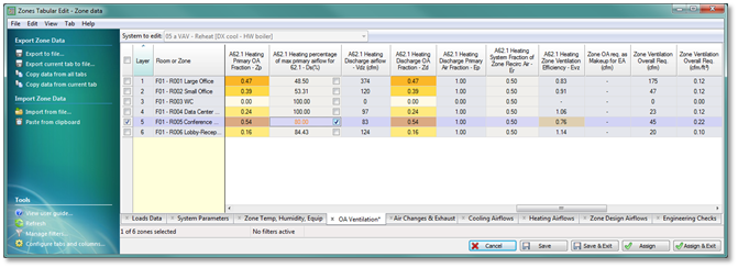
Zones Tabular Edit is a customizable spreadsheet-like dialog for viewing and editing all parameters from the System Parameters dialog (excepting only systems Schedules) for all zones on the system in a single view. This is also the means by which data can be exported for documentation or manipulation in spreadsheets, etc., and can be imported specifically with respect to editable columns of data.
Fields or ‘cells’ for select zone-level parameters use conditional formatting color scheme to draw attention to the zones that are driving system minimum ventilation rates or to draw attention to a value that may be of concern, but which is not strictly speaking in error.
Both the System Parameters dialog and its counterpart, the Zones Tabular Edit dialog, are organized with tabs for system- and zone-level parameters. These are more or less the same tabs and provide access to all of the same parameters; however, the Zones Tabular Edit dialog excludes the system-level ‘Schedules’ tab, subdivides some of the tabs to make the number of default columns more manageable, and places ‘Loads Data’ first.
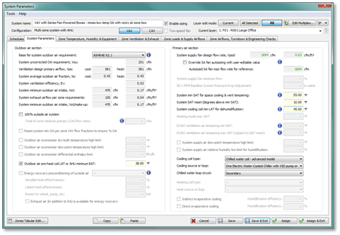
System Parameters dialog tabs (fixed):
· Schedules
· System Parameters
· Zone Temp, Humidity & Equipment
· Zone Ventilation & Exhaust
· Zone Loads & Supply Airflows
· Zone Airflows, Turndown & Engineering Checks
Zones Tabular Edit dialog tabs (customizable):
· Loads Data
· System Parameters
· Zone Temp, Humidity & Equipment
· OA Ventilation
· Air Changes & Exhaust
· Cooling Airflows
· Heating Airflows
· Zone Design Airflows
· Engineering Checks
System Parameter interface toolbar buttons
Toolbar buttons for ‘System Parameters’, ‘Zones Tabular Edit’, and ‘Global System Parameters Assignment’ are the 2nd, 3rd, and 4th buttons on the system sizing section of the ApacheHVAC toolbar shown below:

à

The first two simply open the System Parameters and Zones Tabular Edit dialogs, as described elsewhere. The ‘Global System Parameters Assignment’ simultaneously assigns values from system parameters dialogs for all HVAC networks in the currently open ApacheHVAC file to the components and controllers in those networks.
System Parameter Links
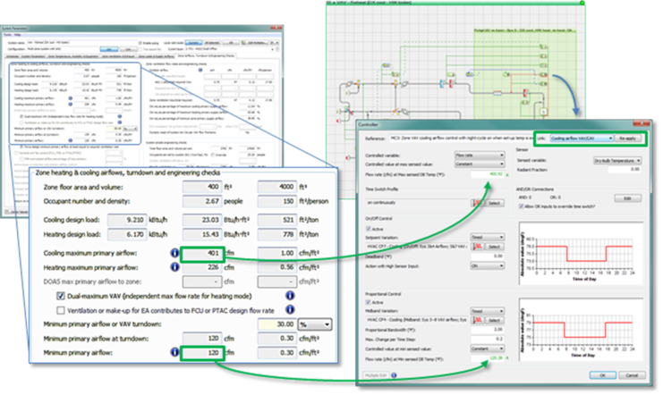
Each parameter in the dialogs is either coupled directly to one or more components or controllers or is used in a calculation within the dialog—i.e., to derive a value for a component or controller. The coupling is provided by unique system parameter links that are set with the individual component and controller edit dialogs.
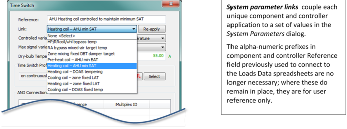
Selecting a particular link within a component or controller determines which values will be assigned to it from the System Parameters dialog. Changing the link or clicking ‘Re-apply’ immediately refreshes the linked values.
The list of available links is context-specific, with its content determined by the component or controller type and, in the case of controllers, by the ‘Controlled variable’ selection in the controller dialog.
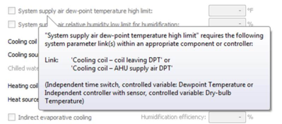
In the System Parameters dialog, parameters are grayed out and disabled when the required link or links are not present within the system frame. Hovering over any parameter that is disabled for this reason provides a ToolTip listing the required links and type of component or controller that they apply to. If a parameter is disabled and there is no such ToolTip, this is because the parameter must be enabled by other means (a checkbox in the dialog, a particular system configuration, or another parameter upon which it depends).
For all prototype systems from the HVAC library, these links are pre-set; however, they can be changed if needed and can be set as desired when adding a new component or control. It is acceptable to completely revise any pre-defined managed system to set up a fully custom system using the links as desired; however, it is recommended that you start with existing prototype system of similar configuration both as an illustrative example and to minimize the additional time and effort required to build the system from scratch.
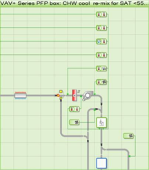
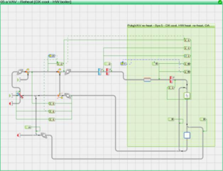
To facilitate use of the System Parameters dialog for editing of component-level values for an HVAC network, HVAC zone components and all other associated zone-level components and controllers within a managed system must be contained in a multiplex, as shown above.
Overriding linked values
Data can still be directly edited at component level via individual component and controller dialogs, overriding settings passed down from the associated system parameters dialog. This may be necessary for departures from system prototypes or to edit parameters not included/editable within the System Parameters dialog. Direct component-level edits to any parameters that are editable in the System Parameters dialog will be overwritten by subsequent ‘Assign’ operations in System Parameters dialog.
Setting the system parameter link to ‘None <Select>’ will preserve any user edits of this nature, preventing them from being overwritten. Selecting any system parameter link or retaining the default link and clicking the ‘Re-apply’ button will override component-level edits.
System Parameter Links – Complete listing
Where links are active, clicking ‘Re-apply’ will refresh the linked values within the component or controller dialog, turning them green to indicate that they have been passed down from the System Parameters dialog. A small fraction of the available links, such as those for Room/Zone components, will not be coupled to any data until associated features and capabilities are added in a subsequent release. Until then, they function only as an informative label for the component or controller. Additional links will be added over time, as part of the evolution of the complete System Parameters interface.
|
COMPONENTS
|
|
Fans
|
Filter
|
Dampers
|
|
None <Select>
|
None <Select>
|
None <Select>
|
|
Supply fan
|
Filter pressure & change
|
Outside air min + econ
|
|
Supply fan – TSP addition
|
|
Outside air no min econ
|
|
Return/Relief fan
|
|
Outside air fixed min
|
|
Exhaust fan
|
|
Outside air variable min
|
|
FCU fan
|
|
Energy recovery bypass
|
|
FPB fan
|
|
Heat-pipe/RR/whl bypass
|
|
Package terminal unit fan
|
|
Zone mixing box damper
|
|
Unit heater fan
|
|
|
|
|
|
|
|
Duct heat gain/loss
|
Heating coils
|
Cooling coils
|
|
None <Select>
|
None <Select>
|
None <Select>
|
|
SA duct heat loss/gain
|
AHU pre-heat coil
|
AHU cooling coil
|
|
RA duct heat loss/gain
|
AHU heating coil
|
FCU/act-beam cool coil
|
|
|
Zone reheat coil
|
PTAC/PTHP cooling coil
|
|
|
FCU/act-beam heat coil
|
UCS cooling coil
|
|
|
PTAC/PTHP heating coil
|
|
|
|
Elec heat coil 2nd stage
|
|
|
|
|
|
|
Heat/enthalpy exchangers
|
Moisture addition/evaporative cooling
|
Thermal battery
|
|
None <Select>
|
None <Select>
|
None <Select>
|
|
Energy recovery HX/wheel
|
Steam humidifier
|
DOAS/AHU cooling device
|
|
Heat-pipe/Run-Rnd/wheel
|
Direct-evap/spray
|
Zone cooling device
|
|
|
Indirect-evap/spray
|
|
|
|
|
|
|
Room or Zone component
|
Room or Zone without air supply
|
|
|
None <Select>
|
None <Select>
|
|
|
Occupied zone (default)
|
Occupied zone (default)
|
|
|
Thermally stratified zone
|
Heated/cooled slab zone
|
|
|
SA/UFAD plenum
|
|
|
|
Return Air (RA) plenum
|
|
|
|
Adjacent room w EA fan
|
|
|
|
INDEPENDENT CONTROLLER WITH SENSOR
|
|
Flow Rate
|
Dry-bulb Temperature
|
Relative Humidity
|
|
None <Select>
|
None <Select>
|
None <Select>
|
|
Cooling airflow VAV/CAV
|
OA econ target & DBT limit
|
Indirect-evap cooling
|
|
Heating airflow VAV/CAV
|
OA econ target reset
|
Direct-evap cooling
|
|
DOAS vent airflow CAV/DCV
|
ER bypass temp target
|
Evap/spray humid per Zn RH
|
|
FCU Cooling airflow CAV/2sp/VAV
|
ER target – cool mode
|
Steam humid per Zn RH
|
|
FCU Heating airflow CAV/2sp/VAV
|
ER target – heat mode
|
|
|
FPB Primary airflow CAV/VAV
|
ER target – PSZ heat-cool
|
|
|
FPB Secondary airflow CAV/2sp/VAV
|
ER bypass temp target -- PSZ
|
|
|
Act bm/IU Primary air CAV/VAV cool
|
Zone mixing variable DBT target
|
|
|
Act bm/IU Primary air CAV/VAV heat
|
Cooling coil – AHU cool LAT
|
|
|
Act beam/IU Induced airflow
|
Cooling coil – AHU dehum LAT
|
|
|
DOAS PTAC/PTHP Cooling airflow CAV/2sp/VAV
|
Cool coil – AHU extend dehum LAT
|
|
|
DOAS PTAC/PTHP Heating airflow CAV/2sp/VAV
|
Cooling coil – AHU supply air DPT
|
|
|
Dual-fan-dual duct zn heat airflow
|
Heating coil – min SAT w reset
|
|
|
PSZ Cooling airflow CAV/2sp/VAV
|
Cooling coil – DOAS tempering
|
|
|
PSZ Heating airflow CAV/2sp/VAV
|
Cooling coil – zone variable LAT
|
|
|
PTAC/PTHP cool airflow CAV/2sp/VAV
|
Cooling coil – full cooling LAT band
|
|
|
PTAC/PTHP heat airflow CAV/2sp/VAV
|
Cooling coil – full dehum LAT band
|
|
|
UCS Cooling airflow
|
Heating coil – full heating LAT band
|
|
|
Cooling-only sys airflow
|
Cooling coil – full h/c LAT band
|
|
|
Heating-only sys airflow
|
Cooling coil – full h/c/dehum LAT
|
|
|
Zone DCV stage1 – VAV ctrl
|
Heating coil – full h/c LAT band
|
|
|
OA min reset - Occupied zone CO2
|
Heating coil – zn fix LAT stage 1
|
|
|
Stratified zn re-mix airflow
|
Heating coil – zn fix LAT stage 2
|
|
|
Wet-bulb Temperature
|
Dewpoint Temperature
|
Percentage Flow
|
|
None <Select>
|
None <Select>
|
None <Select>
|
|
|
|
OA variable min %
|
|
|
|
OA min reset - zone CO2
|
|
|
|
OA min reset - zn VAV flow %
|
|
|
|
OA min reset - Occupied zn VAV%
|
|
|
|
OA min reset - Unocc zn VAV%
|
|
|
|
Zone mixing % primary air
|
|
Heat Transfer
|
Moisture Input
|
Enthalpy
|
|
None <Select>
|
None <Select>
|
None <Select>
|
|
INDEPENDENT TIME SWITCH
|
|
Flow Rate
|
Dry-bulb Temperature
|
Relative Humidity
|
|
None <Select>
|
None <Select>
|
None <Select>
|
|
DOAS vent airflow
|
HP/RRcoil/wheel bypass temp
|
Evap/spray humid SA RH
|
|
CAV airflow – occupied hours
|
RA bypass mixed-air target temp
|
Steam humid SA RH
|
|
CAV airflow – nighttime setback
|
Zone mixing fixed DBT damper target
|
|
|
Min fan airflow
|
Pre-heat coil – AHU min EAT
|
|
|
Zone/RA transfer airflow
|
Heating coil – AHU min SAT
|
|
|
Exhaust/CV hood airflow
|
Heating coil – zone variable LAT
|
|
|
Exhaust driven ventilation airflow
|
Heating coil – DOAS tempering
|
|
|
OA min reset - Unocc zone
|
Cooling coil – zone fixed LAT
|
|
|
|
Heating coil – zone fixed LAT
|
|
|
Wet-bulb Temperature
|
Dew-point Temperature
|
Percentage Flow
|
|
None <Select>
|
None <Select>
|
None <Select>
|
|
|
Cooling coil – coil leaving DPT
|
EA% (vs. return or transfer)
|
|
|
|
EA% available to Energy Recovery
|
|
|
|
RA% to alt path or zone
|
|
|
|
OA fixed %
|
|
Heat Transfer
|
Moisture Input
|
Enthalpy
|
|
None <Select>
|
None <Select>
|
None <Select>
|
ApacheHVAC Workflow using the System Parameters Interface
1) Set up HVAC zone groups and AHU/system groups in model.
2) Edit HVAC schedules and setpoints via the current System Schedules & Setpoints dialog.
3) Load HVAC networks or Managed Systems (having a system frame) from the HVAC library.
4) Set up waterside loops, plant equipment, etc., as desired; or leave this step for later.
5) Set up prototype layers, if desired. This is an optional preparation similar to steps 6 and 7 below, but setting up multiplex layers and system parameters data for types of zone or layers, rather than for specific zones or layers. This can also be done ahead of time in saved user-library prototype systems.
6) Click the ‘Edit Multiplex’ toolbar button or double-click the top bar of the green multiplex frame in a system to assign model zones to the principal room/zone component on each multiplex layer. If prototype layers have been set up, assign zones accordingly to reduce the number of edits to be made later.
7) Click the ‘System Parameters’ toolbar button Double-click the gray system frame to perform edits in the System Parameters dialogs at the level of systems and zones to complete system set-up.
8) Run Room/zone autosizing from HVAC toolbar button or from the ASHRAE Loads dialog.
9) Open the System Parameters dialog again for each system, or via the toolbar and then select the system to edit within the dialog to view and edit the following as needed:
· System input parameters, such as supply air temperatures;
· Zone-level loads, input parameters, and settings;
· Resulting autosized and derived parameters, such as required zone airflows, zone ventilation rates, system flow rates, and engineering checks.
10) Transfer the edits made in System Parameters dialogs to component level using the ‘Assign’ button.
11) Data can be directly edited at component level via individual component and controller dialogs, overriding settings passed down from the associated system parameters dialog. This may be necessary for departures from system prototypes or to edit parameters not included/editable within the System Parameters dialog. Direct component-level edits to any parameters that are editable in the System Parameters dialog will be overwritten by subsequent ‘Assign’ operations in System Parameters dialog.
Setting the system parameter link to ‘None <Select>’ will preserve any user edits of this nature, preventing them from being overwritten. Selecting any system parameter link or retaining the default link and clicking the ‘Re-apply’ button will override component-level edits.
12) Set up waterside loops, plant equipment, etc., if not already completed (step 4).
13) Run System-level autosizing from ApacheHVAC toolbar or from the ASHRAE Loads dialog.
14) View updated derivations as needed in the System Parameters dialog, as the autosizing of the supply fan according to simulated peak coincident flow on each network may have affected these. In some cases, it may be appropriate to override the autosized supply fan flow rate within the System Parameters dialog to match actual fan sizing and to address related engineering checks.
15) If necessary, adjust user setting and inputs, re-assign resulting values to components and controls, and re-run the system-level autosizing.
16) Inspect waterside/equipment dialogs for other autosized values, noting the effects of system sizing with respect to water loops, boilers, chillers, heat pumps, etc.
17) Generate and view System Loads and Sizing reports.
18) Perform simulations and view results.