Steps in performing a VE Compliance analysis
The following workflow is recommended for preparing and performing a compliance or EPC analysis for Part L2 (2013/2014). The plan need not be followed slavishly. Variations can be made in the ordering of the tasks and experienced users may wish to take alternative approaches to some of the stages. The purpose of the plan is to guide you through the basic process.
The workflows for compliance testing and EPC generation follow a similar paths, differing only in the final stages.
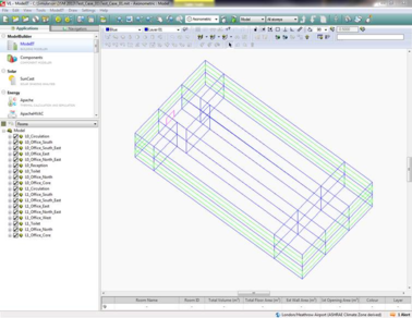
Step 1. Create geometry
The process begins with the entry of building geometry in ModelIT.
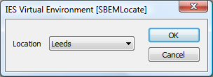
Step 2. Set location and weather data
The building location is specified in the SBEMlocate utility. This is independent of ApLocate.
The L2 regulations currently cover locations in England and Wales.
There are 14 UK locations;
· Belfast
· Birmingham
· Cardiff
· Edinburgh
· Glasgow
· Leeds
· London
· Manchester
· Newcastle
· Norwich
· Nottingham
· Plymouth
· Southampton
· Swindon
The L2 regulations currently specify 11 locations in England and Wales, but the use of any of Edinburgh, Glasgow or Belfast is also permitted if local circumstances make this appropriate.
On the other hand, Part F (Northern Ireland) *requires* the weather location to be Belfast, whilst Part L2 (2014) - Wales *requires* the weather location to be set to Cardiff.
Unlike the ApacheSim route, it is not necessary for a VE-SBEM user to purchase the TRY and DSY weather files from CIBSE as SBEM holds this data internally.
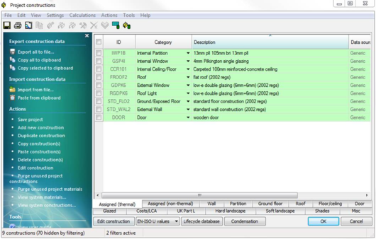
Step 3. Create and assign constructions
Constructions for building elements such as walls, roofs and glazing are created in the Constructions Database (CDB) utility accessible via Apache View or VE Compliance. They should satisfy the U value requirements of Criterion 2. The construction definition should include allowance for non-repeating thermal bridging, using an area-based thermal bridging coefficient. Constructions may be assigned to building elements in either Apache View or VE Compliance.
Note that VE-SBEM assumes the ground floor U values entered in CDB have already been corrected in accordance with EN ISO 13370. This also means the floor area/perimeter method of calculating the ground floor should not be used, because it does not incorporate this correction. (This is different from iSBEM, which does allow uncorrected U values, with SBEM applying the correction internally).
Part L (2013/2014) requires certain attributes to be entered for constructions in addition to the data required for other thermal calculations. The additional attributes (broken down by construction category) are:
Display window?
Tick this box if the window is a display window. Such windows are exempt from certain L2 (2013/2014) requirements.
Transmittances
VE-SBEM requires only the g-value (BS EN 410) and the Visible light normal transmittance (bottom right).
Local shading
This is ignored by VE-SBEM.
External shading
For VE-SBEM only the Sky diffuse transmission factor is required.
Internal shading
For VE-SBEM only the Shading coefficient is required.
Door type
Select from the following types:
· personnel door
· vehicle access or similar large door
· wall or roof element that is not to be treated as a door for the purposes of Part L
· smoke vent
· high usage entrance doors
Doors of types b, d and e form special categories in Part L. Type c is provided to allow door drawing facilities in ModelIT to be used to create wall or roof elements.
Ground floors
Do not use the floor area / perimeter method to auto-calculate U values for VE-SBEM because this does not correct the value in line with EN ISO 13370.
Thermal bridging coefficient
The CDB coefficient is not used by VE-SBEM. The psi values for different junction types (metal clad and non-metal clad) in Building Settings are used instead. Note however that the Metal Cladding setting in CDB will be used by VE-SBEM to determine which of the two possible psi values applies.
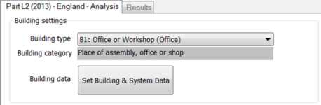
Step 4. Set building type and general data
At this stage you may wish to go to VE Compliance and set up some of the high-level data required for the compliance analysis.
Firstly, check that the Regulatory framework (‘Regs’) selector is set to ‘Part L2 (2013) – England’ or ‘Part L2 (2014) – Wales’.
In the ‘Building settings’ box in the bottom pane select a building type from the list. This indicates the type of building for ratings purposes and determines what room function/activity can be specified in the building and applied to individual rooms. The glazing area is determined by the activity and whether it is side-lit, top-lit or unlit.
For a building with multiple uses, the various parts can be analysed by including NCM activities from other NCM building types in the room-level assignments. This can be done for individual rooms, groups of rooms (using Edit Group Attributes) or via Tabular Room editing.
Not all zones may need to be included in a compliance run. For example separate buildings may exist within the same model. The part(s) of the building included in a particular analysis is defined by the settings of the check boxes ‘Include room(s) in analysis?’ for each room.
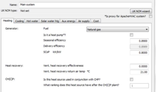
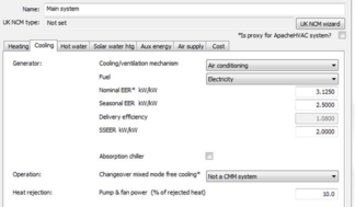
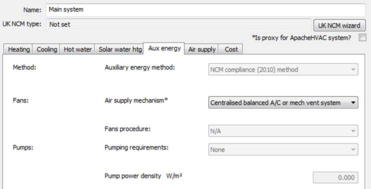
Step 5. Create HVAC and DHW Systems
Within the VE-SBEM method, HVAC and DHW systems characteristics analysis are specified within the framework of Apache Systems.
Systems are one of the aspects of building design where substantial carbon emissions improvements can be introduced. The system data is therefore under your control, and it is shared between the real building (as displayed in the Apache module) and the actual building (as displayed in VE Compliance).
System characteristics for SBEM analyses are defined using dialogs which closely mimic those in iSBEM, the native SBEM interface. The iSBEM manual should be consulted for documentation on these parameters.
The assignment of HVAC and DHW systems to rooms is described in Step 8.
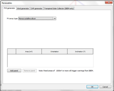
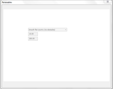
Step 6. Define renewable systems
Five renewable system types are available for use within the SBEM actual building:
· Photovoltaic systems (PVS)
· Wind
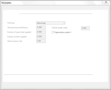
· CHP
· Transpired solar collectors (TSC)
· Solar water heating
The first four are defined on the Renewables dialog (Earth symbol on toolbar) and the last is defined per DHW system on Apache Systems dialog.
CHP should be sized to provide the base load of heating for the building and the power generated will be used to offset the electrical energy usage in the building.
Wind and photovoltaics will, when the prevailing weather conditions permit, provide electrical energy that will offset electrical energy usage in the building.
Note: Solar water heating is not classified as a renewable in the SBEM outputs.
Note: the parameters and models of renewables are different between SBEM and ApacheSim. In most cases the ApacheSim model is more sophisticated.
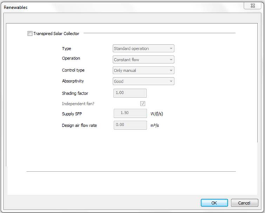
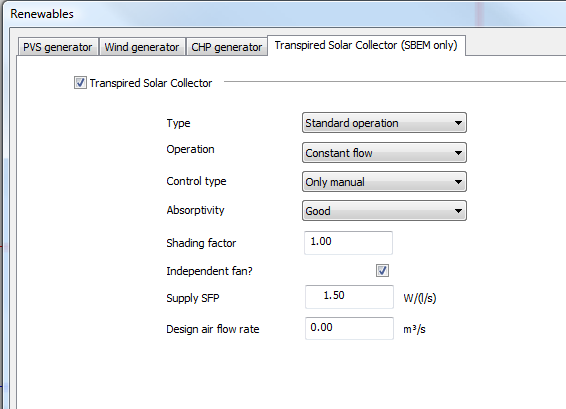
Transpired solar collectors
The properties of the TSC are defined on the following Renewables tab. Note that whereas iSBEM handles multiple types of TSC, VE-SBEM assumes that all TSCs present are of the same type.
Step 7. Create or import room templates
An efficient way to assign Space Data is by means of Thermal Templates. A Thermal Template contains a collection of settings that define the internal conditions applying in a room of a given kind. By defining these conditions centrally you can assign them quickly to large numbers of rooms and transfer them readily to other models via the Import Template mechanism. In the context of the SBEM method this approach is chiefly useful for assigning room activities collectively.
Room Templates contain data arranged on tabs under the headings Building Regulations, Room Conditions, Systems. Not all this data is used in VE Compliance assessments, some being overridden by standard activity settings. It is therefore important to understand where and how the various components of Room Template data are used. In particular, if you do not intend to use the analysis options available in the Apache module (which analyses the real building) you do not need to set Room Template data on the Room Conditions and Internal Gains tabs, or create air exchanges of the Auxiliary Ventilation type.
The NCM Activity, which is always partnered with an NCM Building Type, is one of the attributes that can usefully be set in the Room Template. If this attribute is set in the Room Template, rooms assigned the template will automatically have the NCM Activity (and all the Space Data associated with it) set in VE Compliance.
If you adopt a policy of including NCM Activity settings in your Room Templates you will save a lot of time and effort assigning NCM Activities to individual rooms and groups of rooms in VE Compliance.
Step 8. Edit Space Data
When creating Room Templates it is important to understand which Room Template settings will be used in VE Compliance, which are overridden by standard activity-based settings, and which are editable.
The content of the Space Data tabs and their function in Part L (2013/2014) is summarised below.
General tab
The General tab displays general data about the room, including its name, ID, floor area measures and templates.
The NCM Template is unique to VE Compliance, and is used to import the NCM activity data applicable to the room. Each heated or occupied room (defined using the ‘Type of room’ setting on the ‘Building Regs’ tab) must be assigned an NCM activity. This defines the standard operation pattern of the room for the purpose of L2 (2013/2014), which is defined by attributes on the various Space Data tabs. The assignment of these Space Data attributes is effected by the NCM template corresponding to the activity.
As noted above, it is recommended that the NCM activity is set as an attribute of the Room Template. This saves work as it means that the activity will be automatically set for all rooms assigned that template. An NCM activity is only meaningful in the context of a building type, so this, too, must be set in the template.
If the NCM activity is set in the template it may (like other template settings) be overridden in the room by un-ticking the Template check box and selecting an alternative activity from the drop-down list.
For unheated rooms (those with Type of room set to anything other than Heated room), the NCM activity is undefined and is not displayed. In this case a special NCM template called ‘NCM unheated space’ is automatically assigned to the room.
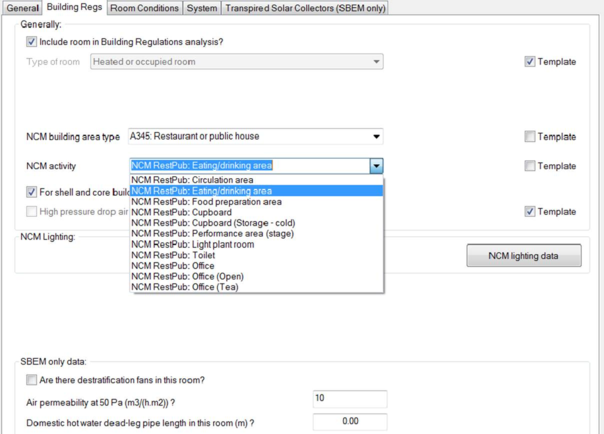
Building Regs tab
This tab is only displayed in VE Compliance. Some of the fields can be set in the Room Template. Others appear only in the VE Compliance Space Data and can be set on individual or group basis, or via Tabular Space Data.
The check box Include room in Building Regs analysis? shown when a room is queried or selected whilst in VE Compliance allows you to restrict the Part L analysis to part of the building only.
The Type of room attribute is normally set to ‘Heated room’, but the following alternative settings are provided to cover various types of unheated space:
· Unheated roof – use this type for an unheated roof space lying outside the insulated building envelope (i.e. where the insulation is at ceiling level).
· Glazing cavity (required only rarely) – use this type for a glazing cavity that has been modelled as a separate room for simulation purposes.
· Unheated buffer space – use this type for other types of unheated space attached to the building but lying outside the insulated building envelope. Examples are car parks and lean-to outbuildings.
· Internal void or warm roof – for SBEM this is not applicable, users should refer to
SBEM guidance on zoning and consider these spaces as indirectly conditioned zones as described in BRE FAQs and documentation.
In the case of the first three types listed above – all representing types of unheated buffer space – an external ventilation rate must also be entered for the purpose of calculating U values for Criterion 2. All the above types of room are excluded from the floor area summation upon which the emission ratings are based but will affect the wall adjacency used by SBEM when considering the conditions of the adjacent heated or occupied rooms that are included in the analysis. All the above types of unheated space are excluded from the floor area summation upon which the emission ratings are based.
The settings NCM Building type and NCM Activity together specify the activity assigned to the room for the compliance analysis, which in turn (via the NCM Template) sets the standard conditions applied for occupancy and plant operation. While these attributes are optional in the Room Template, it is a good idea to set them there to save effort in VE Compliance.
For shell and core building, room is part of core area? relates to the s pecial rules applying to shell and core buildings, rooms belonging to the shell area being treated differently from those belonging to the core area. This box is used (where applicable) to make this distinction.
High pressure drop air treatment does not apply to Part L2 (2013/2014).
NCM lighting data pops the NCM lighting data dialog.
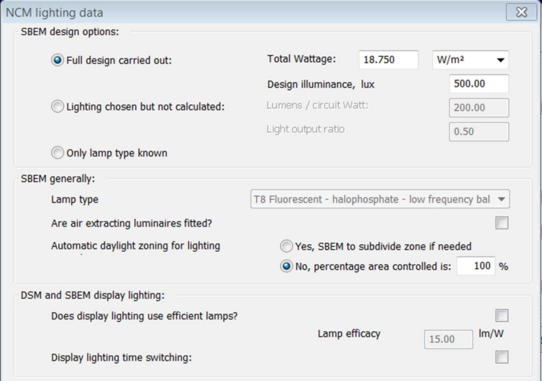
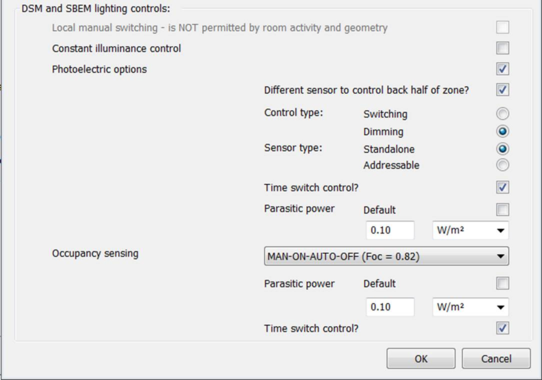
NCM Lighting data dialog
For SBEM purposes this dialog defines the characteristics of both lighting systems and lighting control systems, which SBEM models using the NCM simple lighting control method.
Individual room gains are not displayed when the Method is set to SBEM, so all lighting parameters are set in this dialog.
As the text on the above dialog indicates, all of this data are valid inputs to SBEM. Details are provided in the VE Compliance user guide and the iSBEM 5.2b manual.
Note that in Compliance mode a Full design is required, but in EPC mode the two further options of ‘Lighting chosen’ and ‘Only lamp type known’ become available. The iSBEM manual explains this further.
For all three design options, the EPC mode does require a lamp type to be specified, for the purpose of the Recommendations Report.
Tick Are there destratification fans in this room? to make allowance for this feature in heating demand calculations.
Air permeability at 50 Pa (m3/(h.m2)) specifies the permeability parameter to be used to calculate the room’s infiltration rate (which in SBEM is specified at room level).
Domestic hot water dead-leg pipe length in this room is a parameter affecting hot water distribution losses.
Room conditions tab (data taken entirely from NCM template)
The data set on this tab in the Room Template will be ignored in VE Compliance (but it will be used for assessments of the real building in the Apache module).
In VE Compliance, the data on this tab can be viewed but not edited. It is taken from the NCM Template as part of the specification of standard occupancy and plant operation conditions.
System tab (data taken from Room Template, but editable)
This tab specifies the systems serving the room space conditioning (heating and cooling) and domestic hot water.
Under the heading Systems:
System is the Apache system supplying space conditioning.
Auxiliary vent system is not applicable to VE-SBEM.
DHW system is the Apache system supplying domestic hot water (including any solar water heating system). An individual DHW system is recommended.
Under the heading Heat Recovery (SBEM only):
The type of heat recovery should be selected from the drop-down list, and the Heat recovery seasonal efficiency set to a suitable value.
Under the heading Ventilation & extract:
Is there mechanical supply in this room? should be ticked if the room is served by a mechanical ventilation air supply. This invokes auxiliary energy calculations applied at room level.
Is there local mechanical exhaust in this room? should be ticked if the room has mechanical extract. This invokes auxiliary energy calculations applied at room level.
Scope of extract system feeds into the auxiliary energy calculation. Select as appropriate from the options ‘Fan within zone’, ‘Fan remote from zone’ and ‘Fan remote from zone with grease filter’.
Under the heading Demand controlled ventilation:
The Type of demand controlled ventilation should be selected from the drop-down list.
In the frame dealing with night cooling:
Night cooling? should be ticked as appropriate and the parameters SFP, Max flow rate and Max hrs/mth set appropriately.
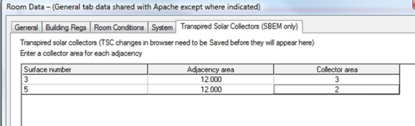
Transpired Solar Collectors tab
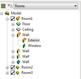
A TSC is assigned to an adjacency in the browser by right-clicking on it (in the same way as a Temperature sensor is assigned in ApacheView). You should then see an orange sun symbol on all three of the adjacency, its parent surface and its parent zone, as shown below.
Important: before going to Space Data to enter the TSC areas, you must Save the browser changes.
On the above tab surfaces are numbered from 1 as they appear in the browser. Adjacencies are identified only by area. If you have multiple adjacencies with similar areas, again the listing order is the same as in the browser. For each adjacency listed, you need to enter a collector area up to a maximum of 90% of the adjacency area.
Do not forget that the TSC properties must be defined under Renewables, see Step 6 below.
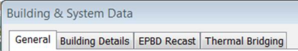
Step 9. Set Building & System Data
We now return to the Building & System Data dialog to prepare for the compliance or EPC simulations. If the ‘Set Building & System Data’ button is not visible at the bottom of the screen, move the cursor into an empty space on the model workspace graphic and click once.
Building & System Data is distributed over four tabs for Compliance and five for EPC.
Under the SBEM framework Building & System Data is distributed over four tabs for Compliance and five for EPC.
Compliance:
EPC:
The Building & System dialog, which may be accessed either via the Building Settings menu ‘Set Building & System Data’ or via the Settings menu, allows you to enter general data relating to the building, its systems and fabric required by the BRUKL and EPC analyses and ratings calculators.
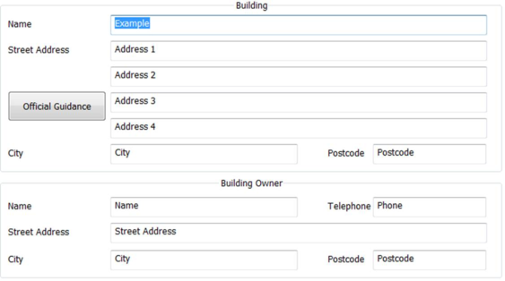
General
This tab takes different forms for compliance and EPC generation. The screenshot below is for EPC generation. For compliance the format is simpler, with the Building and Building Owner sections taking essentially the same form and the Certifier section following the form of the Building Owner section.
These entries provide data general for the BRUKL or EPC ratings calculator. Omitting self-explanatory entries the fields are as follows
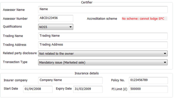
Certifier Assessor number (EPC only): Unique EPC Assessor number, which will be stored in the computer’s registry after an EPC has been successfully generated.
Accreditation Scheme (EPC only): This is the scheme the assessor is accredited wit. Set automatically from Assessor Number.
Qualifications (EPC only): Qualification level of assessor. Must be Level 5 for DSM analysis.
Trading name & Address (EPC only): T he employer or the trading name and address of the energy assessor.
Related Party Disclosure* (EPC only): Any related party disclosure by the Energy Assessor.
Transaction Type* (EPC only): The transaction type which has prompted the generation of the EPC.
*Related Party Disclosure and Transaction Type must be set before an EPC can be generated.
Building Data
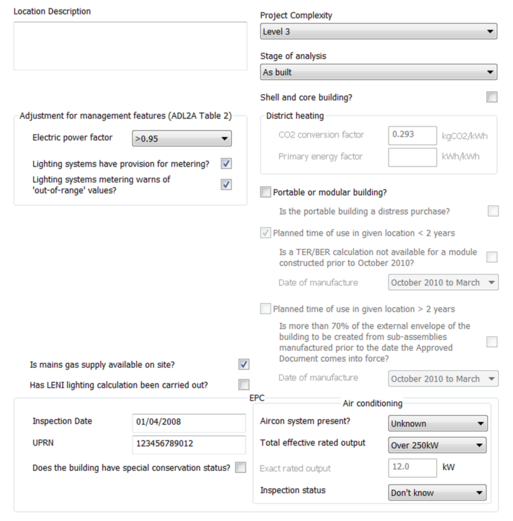
This tab allows for the input of data used in ratings analysis common to the two types of ratings analysis, and certain additional information required for compliance or EPC generation. The screenshot below is for EPC generation. For compliance the format is mainly identical but lacks the ‘EPC’ section.
Location Description
Descriptive text may be entered here.
Adjustment for management features
These settings allow credit to be taken in the BER calculation for management features applied to electrical power and lighting.
· Electric power factor
· Lighting systems have provision for metering?
· Lighting systems metering warns of ‘out-of-range’ values?
Location Description
Give a location description for the building.
Project Complexity
Set the project complexity according to official guidance.
Stage of analysis
Set whether the building is analysed ‘As designed’ or ‘As built’.
Shell and Core Building?
Tick this option to define building as a shell and core building (shell and core rooms as defined on Building regs tab of Space Data)
District Heating
This section is only active when a system with Heat source/fuel type set to District Heating is assigned to a room in the building.
District Heating CO2 Conversion Factor: Enter the CO2 Conversion Factor to be used by systems whose heat source/fuel type is District Heating.
Primary Energy factor: The conversion factor used to calculate the Primary Energy consumption associated with the District Heating system energy use.
Portable or Modular Building
Tick to define building as Portable or Modular and reveal ‘Planned time of use in given location’ and further related input options.
Portable or Modular Building
Tick to define the building as Portable or Modular and set the related inputs Planned time of use in given location and further related input options.
Is Mains Gas Supply Available On Site? (**Applies only to Wales and Scotland)
Should be ticked if mains gas available, un-ticked if not.
Has LENI lighting calculation been carried out? (compliance only)
Specifies whether a calculation following the Lighting Energy Numerical Indicator (LENI) method has been carried out for the building as an alternative to complying with the lighting efficacy standards as specified in the Non-Domestic Building Services Compliance Guide.
The following parameters apply to EPC analysis only
Inspection date (EPC only)
The date on which the energy assessor inspected the building for the purposes of energy calculations for the EPC.
Enter in the format dd/mm/yyyy
UPRN (EPC only)
The Unique Property Reference Number (UPRN) of the building (must be 12 digits).
Does the building have special conservation status?
Tick the box to indicate whether the building has a special conservation status (i.e. the building
has been identified as being: one of special architectural or historical interest, in a
conservation area, in a designated area of special character or appearance, or of traditional
construction).
Air Conditioning
Enter details of the air conditioning system in the building. Not used in calculations (HVAC data is defined in Apache systems/System Wizard) but instead used in EPC report.
Aircon system present? Specify if air conditioning system is present in the building (if applicable).
Total effective rated output: If actual output is known then choose ‘EXACT’ and enter value in ‘exact rated output’ input else choose dropdown option that matches estimated value.
Inspection status: Indicate whether an air conditioning inspection been commissioned for compliance with Energy Performance of Buildings Regulations.
EPBD Recast (compliance only)
Use the inputs on this tab to confirm that consideration has been given to the use of ‘alternative energy systems’ as defined in the recast EPBD.
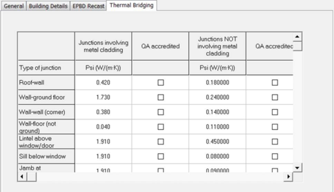
Thermal Bridging
This tab deals with Thermal Bridging which SBEM applies to all external junctions between building elements. Edit the psi values and indicate whether they are QA accredited.
Step 10. Perform compliance or EPC analysis
When you are satisfied that the actual building model is defined as intended, click on the Analysis pane button ‘CO2 Emissions: Part L compliance’ or ‘Generate EPC’. The software will immediately begin the analysis.
The progress of the SBEM calculation is indicated on the screen. Ignore any red text stating “Input file validated? – No” as this is only relevant to iSBEM.
In the case of compliance, results from the actual and notional buildings, together with data provided on the Building & System Data dialog, is then fed into the BRUKL compliance calculator. Results will be displayed on the Results tab.
In the case of EPC analysis, results from the actual and reference buildings, together with data provided on the Building & System Data dialog, is fed into the EPCGen analysis calculator.
When the process is complete a summary of the result of the compliance or EPC analysis will be displayed on the Results tab, and you can click on a button to display the compliance document generated by BRUKL or EPCGen.
A Recommendation Report will also be produced using the details set in Building & Systems Data – dialog, EPC Recommendations tab.
Click the View Recommendation – button to launch the EPC Recommendations as a secure pdf.
Step 11. Review, revise and repeat as necessary
If the result is satisfactory you may move on to the next stage. Otherwise you will need to improve the design and try again.
Step 12. Collate and submit results
Assuming a successful outcome, the Part L2 (2013/2014) compliance analysis (in relation to those aspects of compliance that can be tested before construction) or EPC analysis is now complete.
In the case of compliance the reports generated, together with appropriate supporting evidence, can now be submitted to Building Control.
The content of Part L submissions should be agreed in advance with the local Building Control officer as there may be differing interpretations during the early stages of implementation of the new regulations. These are likely to be resolved over time as a sufficient number of Competent Persons are trained and accredited. It may be necessary, for instance, to agree how compliance with Criterion 4 will be met post construction as part of the pre-Construction report.
In the case of an EPC analysis, the EPC can now be lodged.