Solar water heating (SBEM methodology)
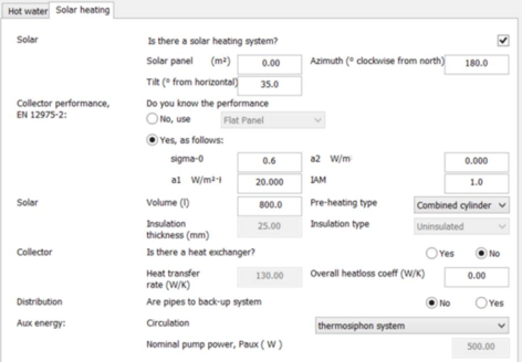
The SBEM methodology models a solar water heating system of the flat plate collector type, using the parameter set shown below.
The parameters have the following meanings (information from the SBEM Technical Manual):
Solar panel area
The solar collector maximum projected area through which un-concentrated solar radiation enters the collector.
Azimuth (° clockwise from north)
The orientation (compass bearing) of the collector (degrees clockwise from north).
Tilt (° from horizontal)
The inclination of the solar collector in degrees from the horizontal, where 0° stands for a horizontal surface and 90° for a vertical surface.
sigma-0
The zero-loss collector efficiency factor (σ 0) from the collector test standards EN 12975-2 and related to the aperture area.
a1
The linear heat loss coefficient from the collector test standards EN 12975-2 and related to the aperture area, in W/m 2 K.
a2
The temperature dependence of the heat loss coefficient from the collector test standards EN 12975-2 and related to the aperture area, in W/m 2 K 2 .
IAM
The incidence angle modifier of the collector from the collector test standard EN 12975-2 when the test angle of incidence between the collector and the direct solar radiation for the test condition is 50°.
Default collector parameters (SBEM Technical Manual Table 28)
|
Collector type
|
sigma-0
|
a1
|
a2
|
IAM
|
|
Unglazed collector
|
0.9
|
20
|
0
|
1
|
|
Flat plate collector
|
0.75
|
6
|
0
|
0.94
|
|
Evacuated tube collector
|
0.65
|
3
|
0
|
0.97
|
Solar Storage
Volume
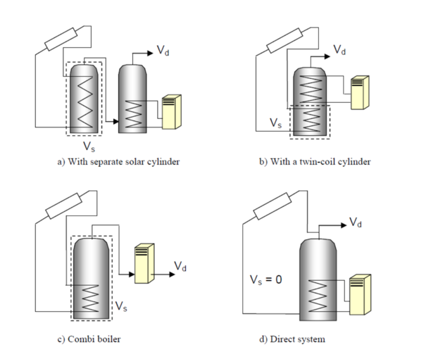
This refers to the dedicated solar storage volume, and it should be calculated according to the arrangements for solar pre-heating as indicated in the schematics in Figure 10 of the SBEM Technical Manual (reproduced below):
· In the case of one or more separate pre-heat tank(s), such as arrangements a or c in Figure 10, the solar storage volume is the volume of the pre-heat tank(s)
· In the case of a combined cylinder, such as arrangement b in Figure 10, the solar storage volume is the volume between the bottom of the lowest back up element (electric element or heat exchanger) to the lowest element of the solar primary.
· In the case of a thermal store (hot water only) where (only) the solar coil is within the thermal store, i.e., no back-up heating, the solar storage volume is the volume of the dedicated thermal storage.
· In the case of a direct system, such as arrangement d in Figure 10, the solar volume should be calculated as 0.3 times the volume of the cylinder. See also Note 2 below.
Note 1
The schematic examples reflected in the Figure 10 are unlikely to represent all types of commercial solar thermal installations. Where necessary, and for more complex systems, an accredited dynamic simulation tool can be used.
Note 2
The dedicated solar volume of a solar thermal installation varies depending on the control and timing strategy of the of the back-up system. To optimise the performance of the solar thermal system, the back-up system should be prevented from operating during and prior to the period of the day where the solar radiation is strong enough to contribute to the hot water requirements. Where it can be demonstrated that the dedicated solar volume should be calculated following a different approach to the guidelines given here, alternative calculations can be used as long as they are in agreement with the UK Micro Certification Scheme standards in effect at that time. The detail and justifications of the calculations undertaken will need to be submitted to the Building Control officer.
Figure 10 of the SBEM Technical Manual -
Arrangements for solar pre-heating
Pre-heating type
Specifies the arrangements for solar pre-heating as one of the following options:
Separate solar cylinder. Dedicated solar pre heating storage: when there is one or more dedicated solar storage vessel that are heated with the solar collectors only and that do not contain any other heating sources.
Combined cylinder. The solar storage is combined in a hot water cylinder with one or more back-up heating sources, i.e., the solar energy system shares the same storage vessel with the hot water system.
Insulation type and thickness
The type and thickness of the insulation of the solar storage tank.
Collector Loop
The solar loop refers to all elements located between the solar collector and the point where the back-up heating source supplies the hot water system with energy. The collector loop parameters are as follows:
Heat transfer rate
Heat transfer rate of the heat exchanger(s) in the solar loop, in W/K.
o For solar thermal direct systems in which the solar primary transmission fluid and the consumed water are the same (arrangement d in Figure 10) the option there is no heat exchanger should be chosen.
o For indirect systems where the primary circuit fluid is different to that of the secondary side of the system, there will be one or more heat exchangers in the storage vessel.
In order to calculate the drop in system efficiency induced by the heat exchanger(s) in the solar loop, the heat transfer rate of the heat exchanger(s) needs to be entered by the user. If this value is not known, the default option should be used.
• For small systems, the heat transfer rate of the heat exchanger in the solar loop value can be obtained from test results according to the standards EN 12975-3 - Performance characterisation of stores for solar heating systems.
• For large systems, the value is taken from the heat exchanger performance data sheet provided by the manufacturer.
• For systems with more than one heat exchanger, using an intermediary or tertiary arrangement such as with a thermal store, an equivalent heat transfer rate should be entered by the user (alternatively, dynamic simulation tools can be used).
Overall heat loss coefficient
The overall heat loss coefficient of all pipes in the solar loop, including pipes between collectors and array pipes and between collector array and the solar storage tank(s), in W/K.
· If the pipe and insulation for the solar loop are known, the overall heat loss coefficient of all pipes in the solar loop can be calculated accordingly - see for instance, John A. Duffie and William A. Beckman: Solar Engineering of Thermal Process. Wiley-Interscience ed., 1991.
· If the pipe and insulation for the solar loop are not known, default values should be used.
Distribution Losses
Are pipes to backup system insulated?
If there are pipes between the solar thermal system and the back-up heating system, the user needs to specify whether the distribution pipes between the solar energy system and the back-up heating source are insulated. This is used to estimate the thermal losses of the distribution between the thermal solar system and the back-up heater.