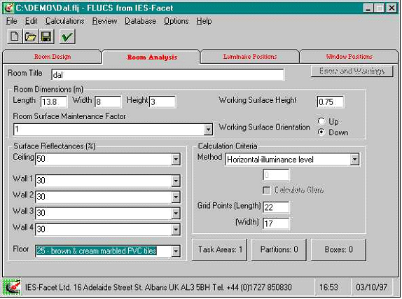
These are used to input the room and calculation criteria for an analysis (point - by - point calculations). The units, and where applicable, default values are shown for each data-item.
Project Title
The project title allows you to describe the project and can be up to 60 characters long. It is printed at the top of the first page of the output.
Room Dimensions
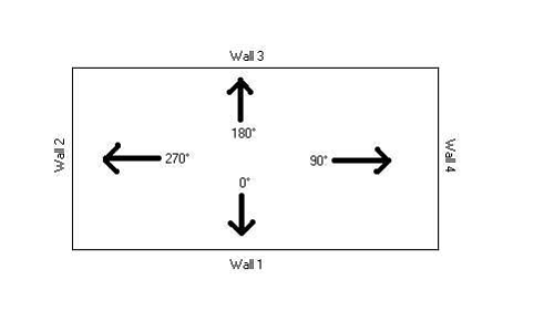
The program assumes a rectangular-shaped room. Walls 1 and 3 refer to the length and walls 2 and 4 to the width as shown below in Fig.1 previously.
Room Length
Units: m
Warning Limits: 2.0 to 100.0
Error Limits: 0.5 to 1000.0
The room length defines the lengths of walls 1 and 3 (see Fig.1).
Room Width
Units: m
Warning Limits: 2.0 to 100.0
Error Limits: 0.5 to 1000.0
The room width defines the lengths of walls 2 and 4 (see Fig.1).
Room Height
Units: m
Warning Limits: 2.0 to 20.0
Error Limits: 0 to 99.0
Enter the height of the room for this analysis. If room height is given as 0.0, the program assumes an external area to be analysed. In this case you will not be asked for surface-reflectance values.
Working-Surface Height
Units: m
Default: 0.75
Warning Limits: 0.0 to 1.20
Error Limits: 0.0 to 9.99
The working-surface height is the level of the illuminated plane.
Room-Surface Maintenance Factor
Default: 0.9
Warning Limits: 0.6 to 0.95
Error Limits: 0.2 to 1.00
The room-surface maintenance factor is the proportion of the illuminance provided by the lighting installation in a room after a set time compared with that which occurred when the room was clean.
Typical room surface maintenance factors are shown in Appendix A, Table 5, and in the CIBSE Code for Interior Lighting, 1994, Table 4.7.
Surface Reflectances
The surface-reflectance value of a surface is the ratio of the luminous flux reflected from the surface to the luminous flux incident upon it. The program will use these values to calculate the ceiling, wall and floor void reflectances, which in turn are used to calculate the internally reflected component.
See Appendix A, Tables 1-3 or CIBSE Code for Interior Lighting 1994, Tables 5.8 and 5.9, for typical reflectances.
If you wish to analyse an exterior area (i.e. you entered the room height as 0.0) you need not enter the surface-reflectance values.
Ceiling Reflectance
Units: %
Default: 70
Warning Limits: 30.0 to 90.0
Error Limits: 0.0 to 100.0
This is the reflectance of the ceiling and not the ceiling cavity. The latter is calculated by the program.
Wall-1 Reflectance
Units: %
Default: 50
Warning Limits: 20.0 to 80.0
Error Limits: 0.0 to 100.0
See Fig.1 for definition of wall numbers.
Wall-2 Reflectance
Units: %
Default: Wall-1
Warning Limits: 20.0 to 80.0
Error Limits: 0.0 to 100.0
See Fig.1 for definition of wall numbers. If a value is not entered here it will default to the value of the previous wall i.e. Wall-1.
Wall-3 Reflectance
Units: %
Default: Wall-2
Warning Limits: 20.0 to 80.0
Error Limits: 0.0 to 100.0
See Fig.1 for definition of wall numbers. If a value is not entered here it will default to the value of the previous wall i.e. Wall-2.
Wall-4 Reflectance
Units: %
Default: Wall-3
Warning Limits: 20.0 to 80.0
Error Limits: 0.0 to 100.0
See Fig.1 for definition of wall numbers. If a value is not entered here it will default to the value of the previous wall i.e. Wall-3.
Floor Reflectance
Units: %
Default: 20
Warning Limits: 10.0 to 50.0
Error Limits: 0.0 to 100.0
This is the actual reflectance of the floor surface and not the floor cavity. The latter is calculated in the program.
Calculation Criteria
The calculation criteria set up the calculation method to be used, which plane is of interest and how detailed the calculations need to be.
Calculation Method
DEFAULT : H
Select horizontal-illuminance, vertical-illuminance, or semi-cylindrical illuminance
All the above are illuminances on the working plane. If the first is used, the illuminance plane is assumed to be parallel to the floor. If one of the others is used, the angle of illuminance plane must be entered.
Illuminance Plane
Units: degrees
Default: WORK PLANE
Warning Limits: 0 to 359
Error Limits: 0 to 359
If the horizontal-illuminance is to be calculated, the illuminance plane is defaulted to the working plane. If the vertical or semi-cylindrical illuminance is to be calculated, the angle of the illuminance plane must be defined. See Fig.2 below for plane-angle definitions:
Figure 2 Plane angle definitions
Glare Calculation
This facility is not yet operational, due to pending changes to the British Glare System and other international standards.
Number of Grid Points in Length
Default: VARIABLE
Warning Limits: 10 to 101
Error Limits: 5 to 101
Enter the number of grid points in the length. This value, together with the number of grid points in the width, determines the resolution of the isolux plots for electric lighting illumination levels. The higher the number, the greater the resolution will be. The default values depend on the room dimensions.
Number of Grid Points in Width
Default: VARIABLE
Warning Limits: 10 to 51
Error Limits: 5 to 51
Enter the number of grid points in the width. This value, together with the number of grid points in the length, determines the resolution of the isolux plots for electric lighting illumination levels. The higher the number, the greater the resolution will be. The default values depend on the room dimensions.
Task Areas
Up to 5 task areas may be defined for uniformity-ratio calculations, which are in accordance with the CIBSE Code for Interior Lighting 1994, Section 4.5.4. The task area is a square of side 0.5 metre, on which is superimposed a grid with 0.25 metre spacing. The task area is embedded in a square of side 1 metre with a similar grid, and the task uniformity and task-surround uniformity are calculated from the illuminances at these grid points.
X-Position of Task-Area Centre
Units: m
Default: Room Length /2
Warning Limits: 1 to (Rm Len - 1)
Error Limits: .5 to (Rm Len - .5)
Enter the distance from wall 2 to the centre of the task area. (Rm Len = Room Length).
Y-Position of Task-Area Centre
Units: m
Default: Room Width /2
Warning Limits: 1 to (Rm Wth - 1)
Error Limits: .5 to (Rm Wth - .5)
Enter the distance from wall 1 to the centre of the task area. (Rm Wth = Room Width).
Partitions
Up to approximately 50 rectangular partitions may be defined to subdivide the room. Each partition is specified by entering the x,y and z co-ordinates of any two diagonally opposite corners of the partition. The x, y and z axes originate at the bottom left-hand corner of the room when viewed from above, with x along the length, y the width and z vertically up.
Partitions are two-dimensional i.e. they have no thickness, and a partition can only be vertical (like a wall), or horizontal (like a false ceiling or floor).
If no task areas are defined, the partition must be parallel to one of the walls.
X-Start
Units: m
Warning Limits: 0 to Room Length
Error Limits: 0 to Room Length
Enter the x - coordinate of the starting corner of the partition.
Y-Start
Units: m
Warning Limits: 0 to Room Length
Error Limits: 0 to Room Length
Enter the y - coordinate of the starting corner of the partition.
Z-Start
Units: m
Warning Limits: 0 to Room Height
Error Limits: 0 to Room Height
Enter the z - coordinate of the starting corner of the partition.
X-End
Units: m
Warning Limits: 0 to Room Length
Error Limits: 0 to Room Length
Enter the x - coordinate of the corner of the partition diagonally opposite the starting corner.
Y-End
Units: m
Warning Limits: 0 to Room Length
Error Limits: 0 to Room Length
Enter the y - coordinate of the corner of the partition diagonally opposite the starting corner.
Z-End
Units: m
Warning Limits: 0 to Room Height
Error Limits: 0 to Room Height
Enter the z - coordinate of the corner of the partition diagonally opposite the starting corner.
Surface Reflectances (%)
This is the ratio of the luminous flux reflected from a surface to the luminous flux incident upon it. The program will use these values to calculate the ceiling, wall and floor-void reflectances necessary for the calculation of the internally reflected component.
Boxes
Up to approximately 50 boxes may be defined to be placed in a room. Each box is specified by entering the x, y and z coordinates of any two diagonally opposite corners of the box.
The x, y and z axes originate at the bottom left hand corner of the room when viewed from above, with x along the length, y the width and z vertically up.
All the sides of the box can only be parallel to the respective room axes.
X-Start
Units: m
Warning Limits: 0 to Room Length
Error Limits: 0 to Room Length
Enter the x - coordinate of the starting corner of the box.
Y-Start
Units: m
Warning Limits: 0 to Room Length
Error Limits: 0 to Room Length
Enter the y - coordinate of the starting corner of the box.
Z-Start
Units: m
Warning Limits: 0 to Room Height
Error Limits: 0 to Room Height
Enter the z - coordinate of the starting corner of the box.
X-End
Units: m
Warning Limits: 0 to Room Length
Error Limits: 0 to Room Length
Enter the x - coordinate of the corner of the box diagonally opposite the starting corner.
Y-End
Units: m
Warning Limits: 0 to Room Length
Error Limits: 0 to Room Length
Enter the y - coordinate of the corner of the box diagonally opposite the starting corner.
Z-End
Units: m
Warning Limits: 0 to Room Height
Error Limits: 0 to Room Height
Enter the z - coordinate of the corner of the box diagonally opposite the starting corner.
Surface Reflectances (%)
This is the ratio of the luminous flux reflected from a surface to the luminous flux incident upon it. The program will use these values to calculate the ceiling, wall and floor-void reflectances necessary for the calculation of the internally reflected component.