Air-source and Water-source VRF systems are available in the Prototype Library as systems 09p and 09q, respectively.
These prototypes include a Dedicated Outside Air System (DOAS) for ventilation, and in both cases the DOAS air handler is set by default to use the first defined VRF system as means of tempering the ventilation air. Users can readily change the coil types in the DOAS air handler if they are not on the VRF system.
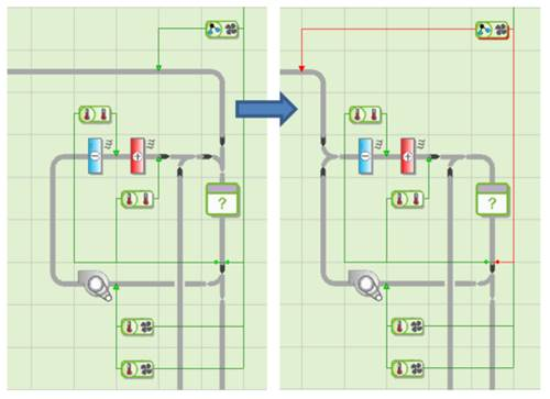
Both of the porotype systems are configured to deliver ventilation air to the zones in parallel with the heating and cooling from the VRF indoor unit. If the ventilation air in the actual system is actually delivered to the back of the VRF indoor units, and thus passes over the coil in that unit along with recirculated room air, the airflow path from the DOAS to the zones should be modified as shown below:
Figure3-128: Modification of prototype VRF systems zone-level configuration to place the airflow path through the indoor unit coil in series with ventilation airflow, rather than in parallel with it.
The water-source VRF prototype system 09q also includes a Heat Transfer Loop with a cooling tower and non-condensing boiler to serve as heat rejection and heat acquisition for the water-source VRF unit (which is equivalent to the ‘outdoor’ unit in an air-source VRF system).