VRF systems are created, edited, and removed via the VRF Systems dialog, accessed by clicking the VRF systems button on the ApacheHVAC toolbar.
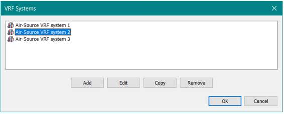
Figure 3-129: VRF Systems list, accessed via the VRF systems button in the ApacheHVAC toolbar
The Add button creates a new VRF system with default settings. The Edit button opens the VRF system dialog for the selected VRF system in the list. The Copy button copies the selected VRF system and adds it to the list as a new VRF system with a unique name. The Remove button deletes the selected VRF system, unless the VRF system is assigned to a VRF indoor unit through a heating or cooling coil. The Cancel button annuls any updates made within the VRF Systems dialog and closes the dialog. The OK button applies any updates made within the VRF Systems dialog to the current HVAC network and closes the dialog.
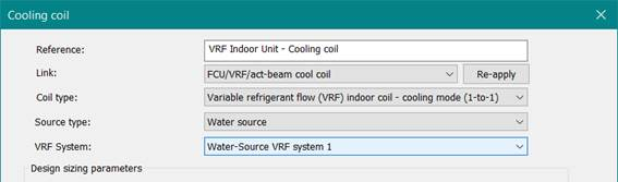
For each refrigerant loop in a VRF system design, that is for each set of refrigerant piping, a unique VRF system should exist in ApacheHVAC. For example, a project with three outdoor units serving different instances of indoor units should be represented in ApacheHVAC with three VRF systems as shown in Figure 3-129, above. Indoor units are then assigned to these VRF systems within the heating and cooling coil dialogs, as shown below for a cooling coil:
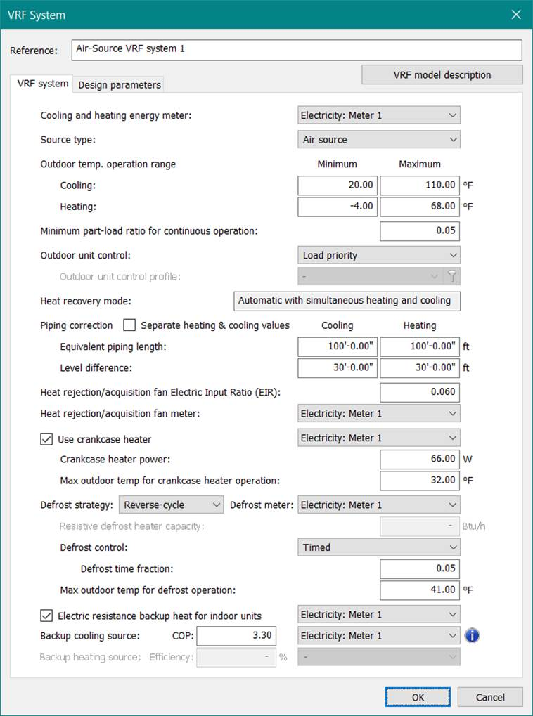
The VRF system tab of the VRF system dialog, accessed by clicking the Edit button for a selected VRF system, allows for the general configuration of the VRF outdoor units, including dictating whether the system should reject/acquire heat to/from an air source or water source. The VRF system tab will have a slightly different set of controls depending on whether the source type is set to Air source or Water source. All controls are defined in the following sections.
Figure 3-130: VRF system editing dialog, shown for an air-source VRF system