Prototype HVAC systems: System types and configurations
The full set of pre-defined HVAC systems in VE 2013 includes the following (Please note that the range of systems offered is expanding with each major release; therefore this list may not include or describe all systems in the Prototype Systems Library:
-
All eight systems required by the ASHRAE 90.1 Performance Rating Method (PRM) with all default equipment, component, and control inputs (including air and water supply temperature resets, etc.) set to 90.1-PRM Baseline values. These generic systems are also provided in a “standard” form that includes a small number of additional features and non-PRM default settings and initial inputs values. Either version of these can be used outside the context of the ASHRAE 90.1 PRM; only those labeled as “PRM Baseline” systems should be used for the baseline model in the context of the ASHRAE 90.1 PRM:
o Packaged Terminal Air-Conditioning (PTAC)
o Packaged Terminal Heat Pump (PTHP)
o Single-zone air-conditioning system with furnace (PSZ-AC)
o Single-zone heat pump system (PSZ-HP)
o VAV-reheat using DX Cooling and HW boiler
o VAV using DX Cooling and parallel fan-powered boxes with electric heat
o VAV-reheat using water-cooled chiller and HW boiler
o VAV using water-cooled chiller and parallel fan-powered boxes with electric heat
o Heat & vent only DOAS with either furnace or electric resistance heat (for 90.1-2010)
These systems meet all ASHRAE 90.1-2007 PRM requirements for baseline systems modeling, including all detailed system-specific requirements. Where equipment performance standards vary with sized equipment capacity or design airflow rates, such values are revised according to PRM requirements at the time of autosizing if the system application is a PRM baseline model (there are a small number of exceptions, such as number of chillers, that still require user intervention). For example, multiple pre-defined DX cooling types are provided for each standard load range and associated COP/EER for DX cooling in systems 03–06. While users can manually select these DX types, in the case of a PRM baseline model, the DX cooling type will be automatically re-assigned to match the COP/EER to the load range as required by ASHRAE.
· Alternate configurations for both PTAC and PTHP systems (four each), supporting different fan-and coil control schemes, ventilation/exhaust airflow paths, and choice of models for DX cooling and small unitary systems, accommodating preference or available performance data.
· Dedicated outside air system (DOAS) with four-pipe fan-coil units, optional demand-controlled ventilation, EWC chiller, and HW boiler.
· Indirect-direct evaporative cooling variant of the basic VAV-reheat system with backup DX cooling and zone-level CO2-based demand-controlled ventilation (DCV).
· VAV-reheat with differential-enthalpy economizer set up for the public areas of a hotel or similar building with PTAC systems for individual guest/resident rooms drawing ventilation air from an atrium zone on the main VAV system.
· Mixed-mode natural ventilation and VAV-reheat with zone temperature and zone CO2 overrides to force mechanical operation whenever nat-vent is insufficient (for example, when not enough cooling or ventilation is provided via operable windows, perhaps because there is insufficient wind, in spite of favorable indoor-outdoor thermal conditions).
· Advanced VAV system with all zones voting on the continuously modulated minimum outside air ventilation rate to ensure that no one zone has insufficient ventilation when load diversity (thus VAV box position diversity) is high and that the system OA is truly minimized when diversity is low. As such, this system also supports lower minimum VAV flow rates.
· VAV with parallel and series fan-powered boxes: The parallel fan-power box configuration is typical (as in ASHRAE 90.1 App. G PRM Baseline systems 6 and 8); the series system includes VAV fan-powered boxes (i.e., assuming variable-speed fan with VSD) and a zone-level mixing damper to temper primary supply air with recirculated air so that the AHU can deliver low-temperature supply air (e.g., 45 F) to the zones.
· DOAS with water-loop heat pumps (WLJPs) sharing a common heat transfer loop (HTL). The HTL can use a wide variety of heat acquisition and rejection devices to maintain common loop temperature within a set range. For example, the HTL includes a water-source heat exchanger for acquiring/rejecting heat to/from a lake, well, ground-water source, or similar. Zone WLHPs freely exchange heat via the HTL whenever simultaneous heating & cooling operation occurs.
· Single-fan dual-duct and with zone-level VAV mixing boxes.
· Dual-fan-dual-duct with zone-level VAV mixing boxes.
· Computer room air-conditioning (CRAC) and computer-room air-handler (CRAH) packaged single-zone systems using DX cooling and chilled water coils, respectively (no heat).
· 100% outside air CAV-reheat system for laboratories featuring specialized temperature controls for maintaining unusually narrow zone temperature control range (while minimized by the coil control scheme, this is at the expense of some reheat owing to the fundamental system configuration). This system also has a second CAV airflow control that maintains a constant airflow rate in unoccupied hours according to the user setting for the Min fan flow rate (typically on the order of 50% for laboratories using this type of configuration).
· Underfloor air distribution (UFAD) displacement ventilation (DV) with parallel fan-powered boxes for perimeter zones, and re-mixing of PFPb zones when they’re in heating mode. Can also be used for thermal displacement ventilation by simply omitting the PFPb’s, UFAD plenum, and re-mixing in heating mode.
· UFAD/DV system as above, plus heat pipe or run-around coil in AHU for free re-heat of sub-cooled (dehumidified) air after the AHU cooling coil.
· Active chilled beams with DOAS for ventilation, both using electric water-cooled chiller with waterside economizer and condenser heat recovery; recovered heat and HW boiler for DOAS heating coil and zone baseboard fin-tube convectors.
· 4-pipe version of the active beams system (chilled and heated beams).
· Advanced variant of 4-pipe active beams system (chilled and heated beams) with multiple zones on a single VAV box for primary airflow, but each zone having separate control over water flow to heating and cooling coils in active beams.
· Radiant heating and cooling panels (i.e., four-pipe system), plus DOAS with airside energy recovery and CO2-based demand-controlled ventilation (DCV).
· Radiant panels and DOAS as above with heat pipe, run-around coil, or heat wheel in AHU for free re-heat of sub-cooled (i.e., dehumidified) air after the AHU cooling coil.
· Heat & vent only DOAS systems with options for gas boiler, furnace, or electric resistance heat and either DCV or constant-volume ventilation.
Loading HVAC systems from and exporting to library or project folders
HVAC Library toolbar buttons
· Load/import HVAC networks from system library, user library folders, and previous projects.
· Export HVAC networks (all, one complete network, selected subset, plant only) to user libraries
Use the load/import from library toolbar button to access the Import dialog shown above and browse the
HVAC Library Import Systems dialog
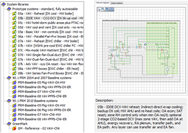
Figure 6-2: ApacheHVAC includes a library of numerous pre-defined, autosizable HVAC systems that can be selected, previewed, and loaded from the dialog shown above. This dialog also provides access to user libraries and project folders and options for inclusion of plant equipment, fuel code/energy end-use types, and profiles referenced in the systems being loaded or imported.
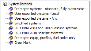
HVAC Library folders
· Prototype systems – standard, fully autosizable: This is the principal and most complete set of autosizable library systems provided with ApacheHVAC.
· User exported systems – Local: User library located in the VE apps/Templates/HVAC folder
· User exported systems – Any: Browse to any user library location or project folder
· Simplified systems: Non-autosizable systems with highly simplified configurations and controls
· 90.1 PRM 2004 and 2007 Baseline systems: Required baseline system configurations and equipment with auto-selection of equipment (e.g., DX cooling types) where feasible and default values set for the ASHRAE 90.1-2004 and 2007 Appendix G Performance Rating Method.
· 90.1 PRM 2010 Baseline systems: Required baseline system configurations and equipment with auto-selection of equipment (e.g., DX cooling types) where feasible and default values set for the ASHRAE 90.1-2010 Appendix G Performance Rating Method.
· Prototype equip, profiles, fuel codes only: This folder contains pre-defined equipment, profiles, and fuel codes for import (e.g., to a user system file), but no airside HVAC networks.
· GreenMark: Required baseline system configurations and equipment with default values set for the GreenMark Performance Rating Method.
HVAC Library systems selection and filtering
Figure 6-3: HVAC systems selection: branches of the library folder tree can be collapsed and expanded; characters entered in the field at the top of the tree can be used to filter the list of files; a description of each system is provided below the tree; and the preview window displays the selected airside network.
Figure 6-4: The Stay in dialog option allows selecting and loading multiple systems without need to re-open the HVAC library dialog, navigate library folder, or reset filtering of the HVAC system files. The auto-placement feature places each subsequent HVAC network to the right (in a row) or below (in a column) any systems already on the canvas. The auto-placement option can be changed at any time.
HVAC Library Import options
Figure 6-5: The Import options tab provides selection of which categories of plant equipment will be loaded, criteria for filtering equipment in each category, and which profiles or fuel-code/energy end-use types, if any, should be loaded with the HVAC system network(s).
Additional systems can be loaded at any time and additional sizing runs performed as needed.
Modifying pre-defined HVAC Library systems
Prototype systems can be modified or used as resources from which to copy elements for customizing or extending the capabilities of a particular system. For all but advanced users, however, it is recommended that initial system sizing and brief test simulations are completed prior to modifying the system configuration, components, or controls (substantial experience with ApacheHVAC is also recommended).
While some autosizing features are constrained to particular component and controller applications or configurations, all of the pre-defined systems can be extensively modified. This includes combining features from multiple systems into one, directly coupling systems, or adding custom component and control configurations.
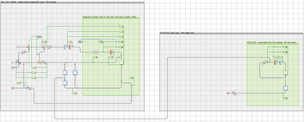
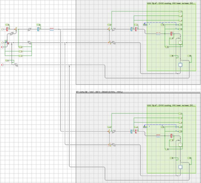
Figure 6 - 6 : HVAC library systems 05c – VAV hotel-dorm public areas plus PTAC rooms and 07i – Multi-AHU - DCV - commonDOAS are examples of system configurations that combine other pre-defined HVAC networks for floor-by-floor applications, cascading airflow, or similar schemes.
Figure 6 - 7 : System 07c – Mix-mode VAVr-NatVent is an example of a more basic system (07a – VAV reheat) with four dependent controllers added to coordinate mixed-mode mechanical HVAC operation with that of operable openings or any of many possible controlled natural ventilation schemes.
For example, the pre-defined DCV controls, heat pipes, or controllers for mixed-mode operation could be drag & drop copied from other pre-defined systems to one of the Active chilled beam systems. The air supply for the system could be drawn from an atrium or other space on another system. The heat recovery could then be modified to model a desiccant wheel regenerated by heat recovered from the condenser loop on the electric water-cooled chiller, which can also me set to use a waterside economizer (waterside free cooling). There are also special features for advanced modeling, such as surface temperature (e.g., ceiling or floor slab) sensors for control of hydronic components.
Airside components—coils, mixing dampers, spray chambers, heat exchangers, fans, flow splitters, etc.—sensors and controllers can be arranged as needed to model custom configurations, such as an earth tube or subterranean labyrinth for pre-conditioning intake air, series or dual-mode rather than parallel fan-powered boxes, a DX cooling and dehumidification system with desiccant wheel regenerated by waste heat from the DX condenser coil, staged dual-max and triple-max VAV controls, specialized temperature resets, or a laboratory with exhaust air changes made up by a combination of supply air and transfer air from adjacent spaces.
All available waterside and plant equipment selections, options, and parameters, including user-defined equipment, can be added or modified within any pre-defined prototype system without detracting from the autosizing and simulation capabilities. (Note that hydronic room units, such as radiators and chilled ceilings, are autosizable within prototype systems as of VE2013; however, these are zone-level features for which autosizing is currently still tied to the Load Data spreadsheet for each system.)
For chillers, boilers, and DX cooling there are both detailed models with editable pre-defined performance curves and models using a matrix of part-load data. There is detailed modeling of chilled water loops, flexible sequencing of separately defined boilers, chillers, and other sources of hot or chilled water, and detailed hot-water and chilled-water coil models with autosize and design sizing modes. There are also editable models for cooling towers and fluid coolers, and various options for modeling pumps on primary, secondary, and tertiary (hydronic unit/zone) water loops.
PLEASE NOTE: This section of the ApacheHVAC User Guide is presently still under construction. Please be sure to check for updates.
Part-load data matrices are provided for modeling generic and non-standard heating and cooling sources. For this type of model, cooling COP can vary both with load and outdoor conditions. Part-load cooling sources can also use the chilled-water loop model and associate pump modeling, but do not share the detailed condenser-water loop and cooling tower models used by the full electric water-cooled chiller model. Like hot-water boilers, part-load heat source models can use recovered chiller condenser heat must presently still modulate associated pump power according to heating load. Any heat source can serve space heating and/or domestic hot water loads, and a solar thermal hot water model with storage tank is available to use as the first source of heat for domestic hot water.
Presently, mapping of results for any given node in the HVAC system on a psychrometric chart must still be done by transferring state points to a separate psychrometric chart tool. However, this data is available for every simulation time step and the Vista Results view supports graphing selected zone and system-level node variables on the same graph. Room conditions and outdoor variables can similarly be added to the same graph. Anything that can be graphed can also be viewed, copied, and exported to other tools as a table of results data for each time step.
The pre-defined systems added in 6.3 include versions of systems 1 & 2 using the more detailed Unitary Cooling System Model, a more advanced configuration of system 5 with enthalpy economizer and directly coupled copies of system 1 for residence/hotel rooms, and a range of eight more advanced “non-conventional” systems. These include the following:
· Packaged terminal air conditioning using the detailed Unitary Cooling System (UCS) model (appropriate for small single-zone units with fixed-speed fans that cycle on and off, such as through-the-wall AC), with a hot-water heating coil coupled to a central boiler.
· Packaged terminal heat pump using the detailed Unitary Cooling System (UCS) model (appropriate for small single-zone units with fixed-speed fans that cycle on and off, such as through-the-wall AC) in cooling mode and an air-source heat pump in heating mode, with electric-resistance backup heating coil.
· Indirect-direct evaporative cooling VAV-reheat system with backup DX cooling coil, dew-point-temperature OA economizer high-limit control, zone-level humidity high-limit control, and CO2-based demand-controlled ventilation (DCV) using zone-level sensors to first force individual VAV boxes further open and the request additional outside air at the system level.
· VAV-reheat with differential-enthalpy economizer set up for the public areas of a hotel, dormitory, or similar building with PTAC systems for individual rooms drawing air from and atrium zone prior to the return path of the main VAV system.
· Mixed-mode natural ventilation and VAV-reheat with zone temperature and zone CO2 overrides to re-introduce system air supply when nat-vent mode is insufficient (e.g., when the room occupancy is very high or wind-driven pressure differentials are too low) in spite of indoor-outdoor thermal conditions that are appropriate for ventilation and cooling via operable openings.
· Dual-fan-dual-duct system with dew-point-temperature OA economizer high-limit control and zone-level mixing boxes (reduces fan energy and avoids the need for reheat, but requires second set of ducts).
· Underfloor air distribution with parallel fan-powered boxes (PFPb’s) for perimeter zones, leakage path, and re-mixing of otherwise thermally stratified PFPb zones when in heating mode.
· Underfloor air distribution as above, plus heat pipe or run-around coil in the AHU for “free” re-heat of sub-cooled (i.e., dehumidified) air after the AHU cooling coil, and accounting for added static pressure seen by the supply fan when airflow passes through the heat pipe/coil (i.e., when it is not bypassed).
· Active chilled beams (zone-level induction units with cooling coils and induced flow in proportion to the primary airflow) and a Dedicated Outside Air System (DOAS) for temperate ventilation air.
· Radiant heating & cooling panels (multiple two-pipe or four-pipe units can be placed in each zone; 2 types are pre-defined for both heating and cooling as examples), plus DOAS with zone CO2-based DCV.
· Radiant panels and DOAS as above with heat pipe or run-around coil in AHU for “free” re-heat of sub-cooled (i.e., dehumidified) air after the AHU cooling coil, accounting for added static pressure seen by the supply fan when airflow passes through the heat pipe/coil (i.e., when it is not bypassed).
All 22 predefined systems will now load via the System Prototypes “S” button in ApacheHVAC and the System Prototypes & Sizing Navigator. When the tabbed views have been provided in ApacheHVAC, users will load these predefined systems individually, as needed.