Principal v's Non-Principal & Principal Rooms
Principal vs. Non-principal multiplex
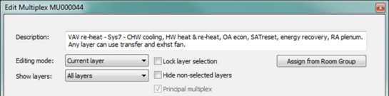
The Principal multiplex must be designated whenever there is a secondary, non-principal, multiplex within the same system frame. The System Parameters dialog will be coupled only to the zone layers, components, and controllers in the Principal multiplex.
The inclusion of secondary, non-principal, multiplex within the same system frame is not permitted for single-zone (system types 03 and 04) or packaged terminal units (system types 01 and 02) which are not coupled to a DOAS (as is system types 09j and 09k).
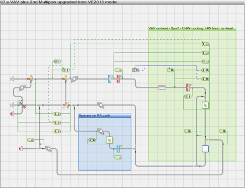
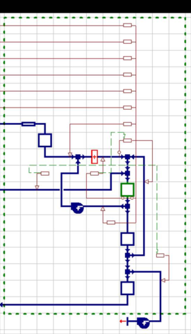
The inclusion of secondary, non-principal, multiplex within the same system frame should be necessary only when there are multiple zones that must be included on the same airside network either before or after, rather than in parallel to, the main set of zones on the system. The network below provides an example of this.
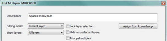
· Non-principal multiplexes will be highlighted in blue, similar to non-principal rooms. For a legacy system having more than one multiplex within the system frame, the multiplex with the greatest number of layers will automatically be set as the principal multiplex when the system is first loaded, and thus upgraded.
· The multiplex dialog has a new ‘Principal multiplex’ checkbox that is visible only if the system contains more than one multiplex. This is forced ticked and grayed out for the current or default principal multiplex, and is enabled and unticked for any non-principal multiplex. These checkboxes function as radio buttons in that only one multiplex can be designated as the Principal multiplex.
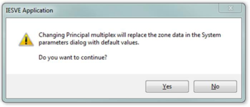
· When checking this box for a currently non-principal multiplex, the following warning message will be displayed on clicking OK in the dialog:
The same message is also displayed if the principal multiplex is deleted, de-multiplexed, or moved out from the system.
· System links set for components and controllers in a non-principal multiplex won’t be coupled to of affect the parameters in the System Parameters dialog, nor will these links assign any data to these components or controllers when you click either of the Assign buttons in System Parameters dialog.
· As the normal behavior of assigning data from System Parameters UI to the component or controller being edited when a system link is first selected would be inappropriate, the system link drop-down selector and re-apply button are hidden for components and controllers in a non-principal multiplex.
· Any single-multiplex legacy system of type 03 or 04 will have its multiplex resized automatically to contain all the components and controllers first time it is loaded in VE2016, thus automatically converting it to be correctly recognized by the System Parameters UI with ‘Single-zone systems’ displayed the ‘Configuration’ field. Any systems of this type containing two or more multiplexes, which is not permissible, will not be upgraded. Instead, the following warning message will be presented to the user:
‘ One or more of the airside networks in this ApacheHVAC file cannot be upgraded as required for use with the ISM System Parameters user interface. These are airside system networks of type 03 or 04, which are meant to be ‘packaged single-zone’ systems. For this system configuration, the upgrade requires that there is not more than one multiplex within the system frame. For single-zone systems, secondary multiplexes can be connected to a primary multiplex, but must be set up either as separate systems (within a separate system frame) or at very least outside of the system frame for the packaged single-zone system.’
Principal Rooms
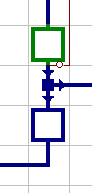
By default, the first room in the multiplex network is nominated as the Principal Room and indicated as a green room component on the network.
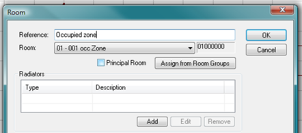
Each layer in the multiplex is assigned a Principal Room to help identify the layer. Double click the Principal Room column for any Layer to select the Principal room from the list of rooms in the model.
Each layer in a multiplex can have more than one Room component on it. All layers, however, must include the same number of Room components. Three examples of this are provided below.
Room components can have duplicate assignments across multiple layers. This is most typically used for non-principal rooms (see examples 1 and 3 below).
Non-principal room components can remain unused on selected layers. This requires only that they are set via their Room assignment to act as an “Adiabatic duct,” rather than being associated with a room or zone in the 3D model (see examples 1 and 2 below).
To change a room component on the network from a non-principal room (blue outline) for all layers to the Principal Room for all layers, double-click the desired room component and then tick the box next to Principal Room within the Room dialog. As this is equivalent to adding or deleting a component, the determination of the component that is the Principal Room must be consistent across all layers in a multiplex.
When including more than one room component on each multiplex layer, the principal Room is typically the occupied space with which a thermostat or other sensors and controls are associated.
Example 1: It is common to have a return air (RA) plenum void in commercial spaces. This should be modeled as a separate thermal zone over top of all of the zones it serves. There may, for example, be one plenum for each floor of the building. These RA plenums would be represented by a non-principal “room” component directly downstream of the occupied space on all multiplex layers. However, the Principal Room component on each layer will typically be assigned a different space in the model. Therefore, if there were one RA plenum for entire 1st floor, it would need to be associated with all occupied thermal zones on that floor, and thus the same RA plenum space in the model should be assigned to the plenum room components on each of the layers that contain a room on the first floor that has a return-air grill.
If there are spaces on the first floor in this example that have supply air and either a ducted return or no return (perhaps they are exhausted), they would not be coupled with the RA plenum. For layers assigned to these spaces, the RA plenum component should be set as an Adiabatic duct.
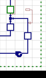
Example 2: There may be a principal room that contains a thermostat (sensors and controllers) and an adjacent room, such as a lavatory, that draws transfer air from the principal room and has no thermostat or other sensors associated with it. There must, however, be means of determining the airflow through it, even if the flow is intentionally set to zero. Typically, such rooms will have a path to either an exhaust fan or a return fan. This will draw air from an adjacent space, as in the lavatory in the illustration to the right.
As it is very unlikely that there would be a lavatory or similar space drawing transfer air adjacent to the Principal Room on every layer, this non-principal room component would be set as an Adiabatic duct on all layers for which it is to remain unused.
Example 3: In the case of an underfloor air distribution (UFAD) system, each layer would typically include the UFAD supply plenum, an occupied zone, a stratified zone, and possibly also a return-air (RA) plenum. The occupied spaces would normally be the Principal Room on each layer. As the UFAD plenum would be before this on the network, the component representing the occupied zone on the network would need to be changed from a non-principal room to the Principal Room for all layers, as described above.
As with the RA plenum in Example 1, each UFAD supply plenum serving more than one zone would be assigned to the designated UFAD plenum component on more multiple layers (the same layers as the occupied zones it serves).
For occupied zones served by the UFAD plenum, there would be a corresponding stratified zone assigned to a non-principal room component downstream of the Principal Room. If there is an RA plenum, this would be yet another non-principal room downstream of the stratified zone.
If there are spaces receiving supply air from the same airside system but not via the UFAD plenum, the UFAD plenum would be set to Adiabatic on those layers. Similarly, if those or other spaces were to be fully mixed zones using overhead diffusers, the stratified zone room component would be set to Adiabatic on those layers.
Assign from Room Group
The Assign from Room Group tool can be used to assign rooms to selected layers. It can also be used to automatically add layers to the multiplex for each room in a selected room group—i.e., to create exactly the number of additional layers that will be required for all rooms or thermal zones in the group.
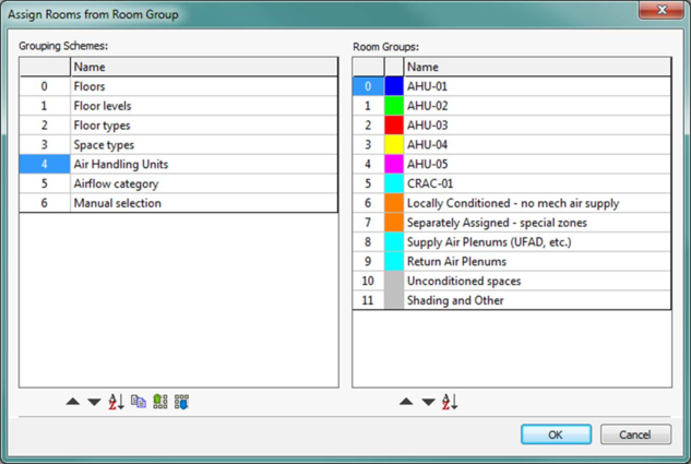
The ‘Assign from Room Group’ button opens the ‘Assign Rooms from Room Group’ dialog showing the Grouping Schemes in the project.
Select a Grouping Scheme and Room Group then click the OK button to assign each room or thermal zone in the selected Group as a Principal Room on a multiplex layer.
Hold the Ctrl key to select multiple groups.
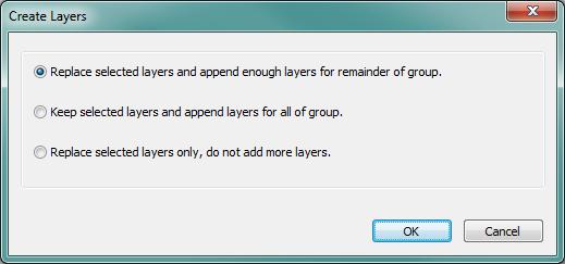
If there are more rooms or zones in the group than layers currently selected in the multiplex, three optons are provided:
1. Replace selected layers and append enough layers for remainder of the group.
2. Keep selected layers and append layers for all of the group.
3. Replace selected layers only, do not add more layers.
Room(s) assigned
The column of check boxes at the right-hand side of the Create/Edit Multiplex dialog indicates whether or not all Room components on a given multiplex layer have been assigned. The check boxes are not user-editable, but will include a check mark when assignments are complete for a layer. Assigning an ‘Adiabatic duct’ rather than an actual space in the model to a Room component does count as an assignment.