Multiplexing HVAC System Networks
Multiplexing allows users to more efficiently create, populate, modify, and edit large ApacheHVAC networks, considerably reducing the project workload. Multiplexing gives users the ability to condense any ApacheHVAC network to a more manageable format.
Multiplex Toolbar
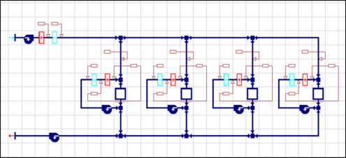
Figure 5 - 1 : Non-multiplexed ApacheHVAC network
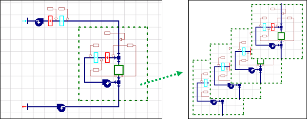
The multiplex feature can be used on a total system level, just at the zone level, or for nearly any other subset of a system (see rules for multiplexes, below). The example below is a 4-zone network with fan-coil units for each zone and a common outside air system. Figure 5-1 shows the network setup without the multiplex feature; Figure 5-2 shows the equivalent multiplexed network.
Figure 5 - 2 : Equivalent ApacheHVAC network with Multiplex. The image on the right is depicting the additional layers that are effectively hidden “under” the currently selected Display Layer.
Multiplex Toolbar
The multiplex toolbar is active when any component or controller in a multiplex is selected.
Create Multiplex
This button opens the Create Multiplex dialog. This is used to add or remove layers, assign principal rooms or zones.
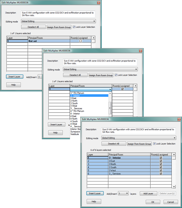
Edit Multiplex
This button opens the Edit Multiplex dialog. This is used to add or remove layers, assign principal rooms or zones, and select layers for editing in the same way as the Create Multiplex dialog described earlier.
Edit Mode
Choose between Local or Global Editing.
Local Edit Mode – edits apply only to the current ‘Display Layer’.
Global Edit Mode – edits apply to ‘All selected layers’, as shown in the Create/Edit multiplex dialog and on the multiplex toolbar.
Number of layers selected
This field displays the number of layers currently selected for edit as a subset of the number of layers in the multiplex—e.g., “6 of 43” means six of the 43 total layers in the multiplex are selected for editing.
Display Layer
The currently active layer is displayed by and can be chosen via this dropdown selector. It is identified by layer number and name of the assigned principal room. It is the editable layer in ‘Local Edit’ (Current layer) edit mode. It is also the layer that will be viewed and serves as the interface in ‘Global Edit’ (All selected layers) edit mode, prior to entering a Data Table component edit or the Zones Tabular Edit view.
Use the up and down arrow buttons to move to the next layer on the list or expand the dropdown to select a layer from the list.
The current display layer can be changed while a room, component, or controller dialog is active, and the contents of that dialog will update to reflect the newly selected layer.
Creating a Multiplex – Overview
A multiplex is created by selecting the Multiplex button in the main toolbar & dragging the green multiplex box from the bottom left to the top right corner of the desired multiplex region. Rules for multiplexes and multiplexed controllers are provided below, following the illustration of basic steps.
Step 1: Position the green multiplex box at the bottom left corner of the area of network that you wish to multiplex.
Step 2: Holding down the left mouse button drag the green multiplex box from the bottom left to the top right of the desired multiplex region and release the button.
Step 3: Once the rectangular boundary for the multiplex region of the system has been dragged over the network components, the Create Multiplex dialog will appear
Rooms or zones in the model are assigned to multiplex layers either by adding layers and manually selecting the spaces from the Principal Room drop-down list on each layer or by using the “Assign from Room Group” feature. These are described in more detail under Create Multiplex, below.
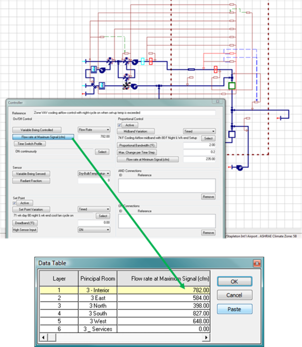
Step 4: Once a multiplex has been created, the network components and controllers can be populated with input values appropriate to the zones and desired control functions on each layer. Calculated flow rates, set points, cooling coil capacities, reference formula profiles, etc. can be entered into the network controllers layer by layer (Local editing), in all currently selected layers (Global editing), or pasted from a spreadsheet into a range of selected layers via a tabular Data Table edit view (Global editing). For autosizing of values within multiplexed components and controllers, see the System Prototypes & Sizing section of this User Guide.
Rules for Multiplexes and controllers within them
When defining the multiplex region, some rules must be followed:
· The multiplexed region of the network must contain at least one room component.
· A multiplex boundary must not abut or overlap an existing multiplex.
· It must satisfy the rules for controllers in a multiplex, as follows;
1. A controller is in a multiplex if its control box is inside the multiplex boundary.
2. Any controller outside a multiplex may only sense or control non-multiplexed nodes.
3. A controller inside a multiplex can sense and control any nodes inside or outside the multiplex.
4. A controller inside a multiplex may not sense and control nodes in another multiplex.
5. AND or OR connections cannot connect a controller in one multiplex to a controller in another multiplex.
· A multiplex must not contain any sections of a network that consist only of connectors (see Figure 5-3 below).
·
Any connection between multiplexes must contain at least one component or junction so that nodes can be generated (see Figure 6-3 below).
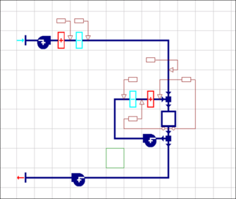
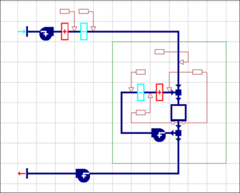
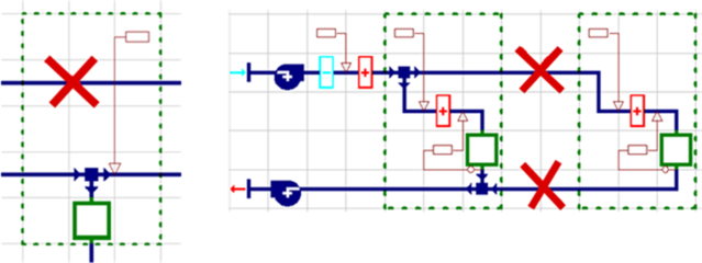
Figure 5 - 3 : Disallowed use of connector segments through a multiplex and between multiplexes
Figure 5-3 provides examples of network branches consisting solely of connecting segments that are not permitted within a multiplex. In cases such as that shown on the left, either re-route the connectors around the anticipated multiplex region or move the controller box downwards so that the multiplex with not overlap the upper path. Direct connections between multiplexes consisting solely of connecting segments (straight or elbow), such as illustrated on the right-hand side of this figure, are not permitted. The network must be revised so that there is a junction or other component between the multiplexes.
Note: It will be common to have multiple-layer instances of a controller pointing to one component control node. In such cases, the controller will “compete” for or “vote” on the value of the controlled variable at every simulation time step. The value that prevails depends upon the controlled variable and type of component being controlled. For example, while the highest temperature will prevail in the case of a heating coil, the lowest temperature will prevail for a cooling coil.
Warning: Where multiple airflow controls are present on one branch, these must all point to the same node if their operation will ever compete for control. An attempt to simultaneously control airflow from two different nodes on a single branch will result in an over-constrained flow.
Create Multiplex
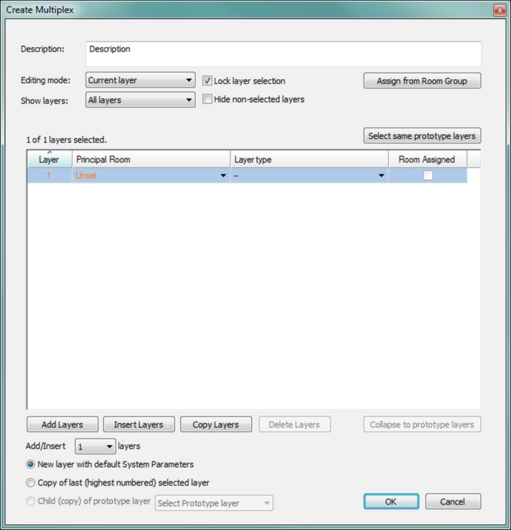
When a new multiplex is created by defining its boundary, the Create Multiplex dialog is displayed. The name and description of the multiplex, the number of layers contained in the multiplex, and the principal room assignment to each layer are entered here.
Figure 5 - 4 : Create Multiplex dialog shown as seen prior to adding any layers or zones.
Description
Enter a name and description here to identify the multiplex and manage complex systems.
Layers
A principal room or zone is assigned to each layer. This can be done for an individual layer via the dropdown selector in the Principal Room/Zone column on any layer row.
Assign from Room Group, as described the section dedicated to that below, is the most efficient way to add and populate the correct number of layers in a system multiplex with a single action.
Alternatively, select the number of layers to be added to or inserted into the multiplex and click Insert Layers (new layers are inserted at the selected layer) or Add Layers (layers are appended to the bottom of the list).
Select layers then click Delete Layers to remove them from the list (note: it is not possible to delete all layers from a multiplex, but all room/zone assignments can be removed).
The Ctrl and Shift keys are used to add or remove individual layers to or from the current selection set and to hold the view from scrolling when there are more layers than can be viewed at once.