This dialog defines lighting the characteristics of control measures which are to be modelled using the NCM Simple Lighting Control method.
This dialog is shared between the ApacheSim and SBEM based ratings frameworks. The following description is limited to the settings applicable to ApacheSim.
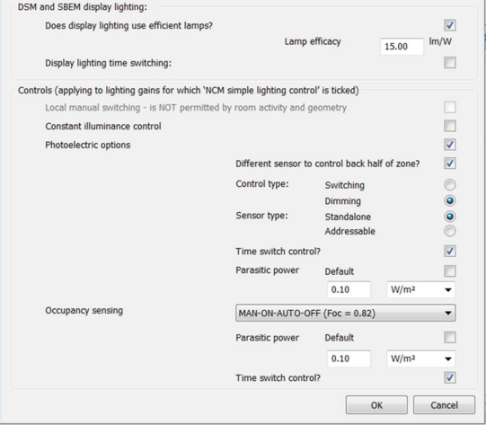
DSM and SBEM display lighting
Does display lighting use efficient lamps?
Tick this box to set the Lamp efficacy for display lighting. In other cases a default value will be used.
Controls (applying to lighting gains for which ‘NCM simple lighting control’ is ticked)
Local manual switching
When permitted by the NCM rules, local manual switching may be selected by ticking this box.
Constant illuminance control
Ticking this box causes an allowance to be made for constant illuminance control, reducing lighting energy.
Photoelectric options
Ticking this box simulates photoelectric control of lighting in response to daylight.
Different sensor to control back half of zone?
Ticking this box improves the quality of photoelectric control by adding a second sensor.
Control type
Select ‘Switching’ or ‘Dimming’.
Sensor type
Select ‘Standalone’ or ‘Addressable’
Time switch control?
Tick the box to turn off parasitic power at times when the lighting profiles are off.
Parasitic power
Set the parasitic power value in W/m2. Parasitic power set with this parameter applies to both photoelectric and constant illuminance control.
Occupancy sensing
Select from options specifying combinations of manual and automatic occupancy sensing control.
Parasitic power
Set the parasitic power value for occupancy sensing control in W/m2.
Time switch control?
Tick this box to turn off parasitic power at times when the lighting profiles are off.
Room Conditions tab
All the data on this tab is taken from the NCM template and cannot be edited.
This data specifies the set points and profiles for heating and cooling and the hot water consumption rate. The parameters are documented in the VE Compliance user guide.
System tab
All the data on this tab is under your control, though set initially from the Room Template. Much of the data displayed here is shared with other VE views such as Apache View and other Regulatory Frameworks within VE Compliance. The room should be assigned an Apache System with properties accurately describing the system proposed for the actual building.
The following System tab attributes that would normally appear in the ‘System outside air supply’ frame are, however, hidden from view in Part L2 (2013-2014):
· Flow rate
· Variation profile
The reason is that a specification of scheduled minimum ventilation forms part of the standard room conditions associated with the NCM activity (which is handled via data on the Air Exchange tab). To avoid a double specification of minimum ventilation the System tab ventilation parameters are disabled for ratings analysis.
Ventilation & extract
Mechanical supply
This option becomes active when the Apache System serving the room has Cooling/mechanical ventilation mechanism set to ‘Mechanical ventilation’. In other cases it is disabled.
Mechanical exhaust
This option allows setting mechanical ventilation for the selected zone. Specify the Exhaust flow rate together with the Specific fan power. Care should be taken to set vales appropriate to the system serving the room, as this is not done automatically in the course of system assignment.
Demand controlled ventilation
Where there is demand controlled ventilation, select a suitable option from the drop-down menu.
Internal Gains tab
All of the data on this tab is initially set from the NCM template.
Unlike the NCM template data on the Room Conditions tab, however, aspects of this data may be edited in certain circumstances.
The NCM activity room conditions specify levels and schedules (profiles) for internal gains and (where relevant) electrical consumptions associated with lighting, equipment and occupancy. These gains are automatically set on the Internal Gains tab as a function of the NCM activity.
Lighting gains and consumption, however, are a special case. The NCM activity specifies lighting levels in terms of lux. In the NCM template these are translated to W/m2 using a fixed conversion factor – the Installed Power Density. The value of this factor depends on the activity. It is 3.75 W/m2 per 100 lux for office, storage and industrial spaces and 5.20 W/m2 per 100 lux for other spaces. If the luminous efficacy of the lights in the building differs from the figure assumed in the NCM activity, it is permissible to adjust the lighting power consumption by editing the Installed Power Density.
To do this it is first necessary to un-tick the Template box attached to Design Illuminance. When this is done a parameter ‘NCM Database Illuminance’ appears, together with a Template box that allows the Design Illuminance to be edited to a value derived from a detailed lighting design. In accordance with the rules set out in the Modelling Guide, any value of design illuminance which is less than the database illuminance must be replaced by the latter value, and the interface imposes this condition automatically.
In the ‘lux’ input mode the Luminaire Efficacy is derived using geometry-related rules set out in the Modelling Guide, and the Light Output Ratio (the ratio of Luminaire efficacy to Lamp Efficacy) is editable. The Luminaire and Lamp efficacies are output to BRUKL and appear on the compliance report.
Another way to adjust the Installed Power Density is by setting Input mode to Inference. This allows the lighting properties to be inferred from a Lamp Type. The Lamp Type may also be left Unset, in which case a Lamp Efficacy and Light Output Ratio can be entered by hand.
Ticking the check box labelled ‘NCM simple lighting control’ activates NCM simple lighting control, the details of which are documented in section 5.3 of this guide under the heading ‘NCM lighting data dialog’.
It is also possible to simulate lighting control using a Dimming Profile which has been defined using a formula profile linking the lighting level to room daylight illuminance values calculated by Radiance.
Air Exchange tab
Data on this tab is partly taken from the NCM template and partly user-supplied. The rules are as follows.
The NCM activity specifies a minimum ventilation regime for the activity in terms of a flow rate and a profile. This appears as an air exchange of type Auxiliary Ventilation, taken from the NCM template. The NCM minimum ventilation regime applies to all heated and occupied rooms, whether air conditioned, mechanically ventilated or naturally ventilated.
Auxiliary ventilation assigned to the room by the user in other Views (via the room template or room-specific assignments) is automatically removed. This is to avoid a double-specification of minimum ventilation requirements.
Infiltration is also subject to a special treatment in VE Compliance, being derived from permeability and other parameters specified in the Building & System Data dialog.
Further guidance on ventilation settings in VE Compliance simulations is provided in Appendix A.