What are Opening Types?
In the Virtual Environment, an opening is a window, door or hole that exists in the 3d model geometry as created, for example, in ModelIT. These objects may also be used to represent other types of openings in the building fabric such as louvres and grilles.
Opening Types provide a means for specifying the air flow characteristics of windows and doors for the purpose of analysing natural ventilation and infiltration in MacroFlo.
The air flow characteristics of an opening include its crackage, openable area and exposure to the outside environment, as well as parameters indicating how its area varies with time and (optionally) with room temperature.
These openings are treated in MacroFlo as sharp edge orifices with a fixed discharge coefficient of 0.62. The MacroFlo Opening Types dialog assist users in selecting an appropriate equivalent area % for their opening type. The equivalent area is the area of a sharp edged orifice through which air would pass at the same flow rate, under an identical applied pressure difference, as the opening under consideration. Thus the equivalent area % is the equivalent area of the opening type expressed as a percentage of the opening drawn in the Model. Typically this will be less than 100% to allow for immovable elements such as the frame and obstructing pivoting elements, but can be greater than 100% to allow for scenarios whereby the fixed discharge coefficient of 0.62 is not appropriate.
The pressure / flow characteristics of openings such as louvres and grilles are widely available from manufacturers (coefficient of discharge or Cd factors); however these properties are not readily available for windows. MacroFlo provides a default selection of pressure / flow characteristics for a wide range of opening types for the convenience of the <VE> user.
Holes represent a special category of opening with constant and un-modifiable air flow characteristics, and are not associated with Opening Types.
MacroFlo Opening Types are attached to openings in the model using facilities provided in the MacroFlo Application View.
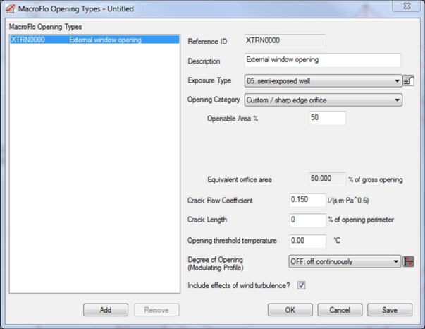
MacroFlo Opening Types Manager Interface
Add
Add an opening type to the list. The initial properties of the new opening type will be copied from the currently selected type.
Reference ID
An 8-character ID unique to the Opening Type. The Reference ID is constructed automatically by the program from the Description.
Description
A verbal description of the Opening Type.
Exposure Type
Select an Exposure Type from the list to specify the exposure of the opening to wind pressures. For details, see help on Wind Pressure Coefficients and the MacroFlo Methods manual. For buildings of more than 12.5m in height, use exposure types with names beginning ‘High-rise’. If the Opening Type is to be used for internal openings only, or if the effects of wind are to be ignored, select ‘Internal’.
Opening Category
Select the category of opening to be represented by the type. Choose from custom/sharp edge orifice, window/door – side hung, window – centre hung, window – top hung, window – bottom hung, parallel hung windows/flaps, window – sash, sliding/roller door, louvre, grille, duct or acoustic duct.
Custom/sharp edge orifice is an idealised model of the real air flow/resistance that occurs through building windows, doors and louvers which in reality involve more turbulent flow.
To specify a realistic opening type in terms of real air resistance select the category and define the parameters that are displayed to calculate the Equivalent Area as a % of the gross opening area as drawn in ModelIT.
Openable area and modeled elements:
Typically users draw a different level of detail at different stages in the design process e.g.
· Early stage – large ModelIT surface elements representing a gross structural opening of which some sub areas may be openable;
· Detail stage – many small ModelIT surface elements each representing an openable (or fixed window) element.
In the examples above openable area may need to include the impact of frame area or obstructing elements in the openable area and/or define the openable area in a large element that contains both openable and fixed parts.
It is important not to confuse openable area with geometric free area which may not be in the plane of the wall.
Custom/Sharp Edge Orifice
Openable Area %
All openings in MacroFlo are treated as sharp edged orifices with a discharge coefficient of 0.62 during the simulation. For all of the other opening types the user inputs characteristics for their opening (openable area, max pivoting angle etc.) which are then converted into an equivalent orifice area by the opening types dialog. For the Custom/Sharp Edge Orifice opening type the openable area % equals the equivalent area %. Thus, the user themselves enters the equivalent area as a percentage of the gross area of the opening in the model.
When using the Custom/Sharp Edge Orifice category for windows and doors which open by pivoting, this equivalent area should allow for immoveable elements, such as frames and areas which do not pivot, and also the obstructing effect of the pivoting element which can result in additional aerodynamic constriction in excess of that found in a sharp edged orifice. As such, the openable area should typically be less than 100%.
Openable areas greater than 100% may be assigned in scenarios where the discharge coefficient of 0.62 may be not be appropriate. See the MacroFlo Calculation Methods User Guide for further details.
Pivoting Window/Door
Windows and doors which open by pivoting can be input using one of the appropriate pivoting opening types, these are:
- Window / Door – Side Hung
- Window – Centre Hung
- Window – Top Hung
- Window – Btm hung
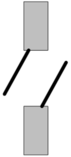
- Parallel hung windows / flaps*
*Parallel hung refers to the type of window shown here;
Openable Area %
The area of the pivoting element of the window/door, expressed as a percentage of the overall plane area of the opening drawn in the model. The value should usually be less than 100%, to allow for window frames and immoveable window elements.
Max Angle Open
The maximum angle of opening of the window/door in degrees. Lower values result in a reduced area available for flow, and hence a smaller discharge coefficient and equivalent area %. Conversely, higher values result in an increased area available for flow and hence a larger discharge coefficient and equivalent area %. For windows which are restricted to opening angles below the minimum angle available, the user must themselves calculate an appropriate equivalent area for their opening and input this using the Custom/Sharp Edge Orifice opening category.
|
Opening Category
|
Min Angle (°)
|
Max Angle (°)
|
|
Window / Door – Side Hung
|
10
|
90
|
|
Window – Centre Hung
|
15
|
90
|
|
Window – Top Hung
|
10
|
90
|
|
Window – Btm hung
|
10
|
90
|
|
Parallel hung windows / flaps
|
15
|
90
|
Proportions
The ratio of window/door length to window/door height. This parameter affects the discharge coefficient (Cv) for the window and as such altering it will alter the Equivalent orifice area %.
Equivalent Orifice Area %
The Equivalent Orifice Area % represents the actual sharp edge orifice area as a % of the gross physical opening drawn in the model through which air will pass at an identical flow rate, under an identical pressure difference, to the opening in question. This is calculated based on the values chosen for the selected opening type.
Sliding Windows and Doors
Windows and doors which open by sliding can be specified using one of the appropriate sliding opening categories, these are:
- Window – Sash
- Sliding/ Roller Door
Openable Area %
The openable area for sliding elements is given by the cross sectional area presented by the opening to air passing through it, expressed as a percentage of the gross opening area defined in the model geometry. This value should usually be less than 100%, to allow for window frames and partial opening.
Equivalent Orifice Area %
The Equivalent Orifice Area % represents the actual sharp edge orifice area as a % of the gross physical opening drawn in the model through which air will pass at an identical flow rate, under an identical pressure difference, to the opening in question. Sliding Windows and doors have a fixed discharge coefficient of 0.65 representative of a fully open window and the equivalent orifice area will be equal to the openable area adjusted to account for the difference between this discharge coefficient and that for a sharp edge orifice.
Grilles, Louvres and Dampers
Grilles, Louvres and Dampers for which discharge coefficients are available can be specified by choosing one of the appropriate opening categories, these are:
- Louvre
- Grille
Openable Area %
The openable area for these opening types is defined as the “Geometric Area” in EN12101, that is:
The area of the opening through a ventilator, measured in the plane defined by the surface of the construction works, where it contacts the structure of the ventilator. No reduction will be made for controls, louvers or other obstructions
This should be expressed as a percentage of the gross opening drawn in the model and will typically equal 100%.
Coeff. Discharge
The coefficient of discharge for the opening given in the available product literature. The coefficient of discharge is defined as:
The ratio of actual flow rate, measured under specified conditions, to the theoretical flow rate through the ventilator
Coefficients of discharge between 0.0 and 0.6 can be specified.
Equivalent Orifice Area %
The Equivalent Orifice Area % represents the actual sharp edge orifice area as a % of the gross physical opening drawn in the model through which air will pass at an identical flow rate, under an identical pressure difference, to the opening in question. This will be based on the openable area % defined for this opening type and adjusted to account for the difference between the discharge coefficients for a sharp edge orifice (0.62) and the ventilator in question.
Ducts
Ducts can be specified by specified by selecting one of the appropriate duct opening categories, these are:
- Duct
- Acoustic Duct
Duct opening categories assigned to an opening take into account pressure drop at both ends of the duct and also pressure losses along the length of the duct. Thus when physically drawing the duct in the model, the duct opening type should only be assigned to one end of the duct as this accounts for the pressure drop across the entire duct including losses at both ends.
Openable Area %
This is the gross face area of the duct opening expressed as a percentage of the opening drawn in the model and will typically equal 100%.
Duct Length
This is the total length of the duct from inlet side to outlet side. Duct length can be any value from 1m to 10m.
Duct
Properties of the duct which influence the pressure drop across the duct are specified here. For the opening category ‘duct’ the properties specified are the number of bends (assumed to be square bends) and the grille free area %.
For the opening category ‘acoustic duct’ the properties specified are whether the duct is straight or angled, the free area of the duct (expressed as a percentage), and the free area across the grille (expressed as a percentage).
Equivalent Orifice Area %
The Equivalent Orifice Area % represents the actual sharp edge orifice area as a % of the gross physical opening drawn in the model through which air will pass at an identical flow rate, under an identical pressure difference as the duct in question. This will account for both in line losses through the duct (dependent on duct type and length) and also end losses at both ends (dependent on grille properties selected).