In ApacheHVAC, the term “Radiators” covers a broad range of hydronic heating devices placed directly in conditioned spaces. These generally include cast-iron radiators, radiant panel heaters, fin-tube convectors, and so forth. Whether mainly radiative or purely convective heating units, the common thread is that all room units are independent of the airside network and airside components; they directly interact only with the conditioned space and the plant equipment.
Radiator room units can also be used as a hydronic loop within a heated slab zone, but care should be taken in such cases to appropriately define the “type” using parameters that will represent the properties of just the hydronic loop within the slab.

Toolbar button for hot water radiator types dialog
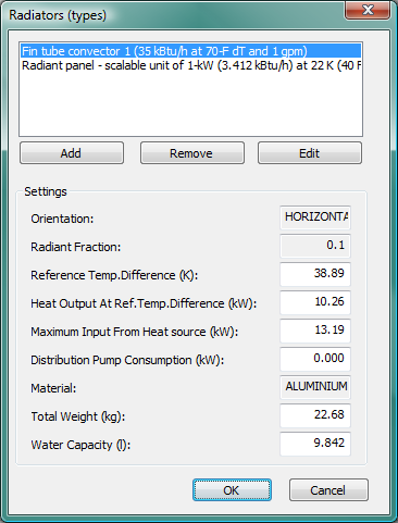
The Radiators (types) dialog supports defining radiator types for placement in the building. Each time a particular type is placed within a room component, this constitutes an additional instance of that type. Any given room can have more than one type and can have more than one instance of a particular type. However, keep in mind that a separate controller is required for each instance. Therefore, it is often worth limiting the number of instances to just one or two per zone by representing a range of grouped sets of radiators with types that represent their collective capacity and related characteristics.
Hot water radiators use the same calculation algorithms as the chilled ceiling module. The variation of convective heat transfer with radiator temperature is modeled using Alamdari and Hammond equations.
ApacheHVAC allows modeling of both TRV and modulated temperature controlled radiators. The program uses a simple parametric model that includes thermal mass and convective heat transfer coefficient that varies with radiator-to-room temperature delta-T.
Figure 5 - 3 : Radiator types dialog with pre-defined illustrative set of convective fin-tube baseboard heaters currently selected.
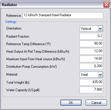 Figure 5 - 4 : Radiator editing dialog showing inputs for a group of small wall-mounted steel radiators.
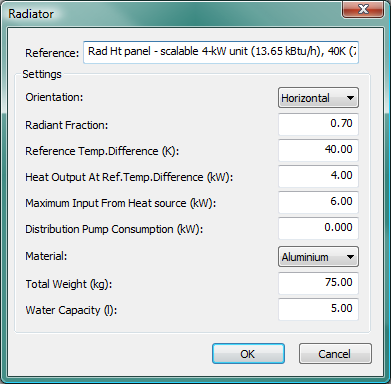
 Figure 5 - 5 : Editing dialog with for pre-defined scalable 4-kW unit overhead radiant heating panel (the 4-kW capacity is matched at conditions in the Reference with the pre-defined scalable 1-kW cooling panel).
Reference
Enter a description of the component. The reference is limited to 100 characters. It is for your use when selecting, organizing, and referencing any component or controllers within other component and controller dialogs and in the component browser tree. These references can be valuable in organizing and navigating the system and when the system model is later re-used on another project or passed on to another modeler. Reference names should thus be informative with respect to differentiating similar equipment, components, and controllers.
Orientation
Select an orientation to describe the orientation of the radiator. Standard radiators are vertically orientated, which will tend to increase the convective heat transfer coefficient within the overall heat transfer calculation. Use horizontal orientation when modeling an overhead radiant panel or a hydronic radiant heating floor system.
Vertical radiators or panels are mainly convective and horizontal radiators or panels are mainly radiative in their effect. The selected option therefore affects the default radiative fraction in the next cell. It is also used as a parameter to the Alamdari and Hammond convective heat transfer coefficient equations in determining the variation of the convective heat transfer coefficient with radiator/panel temperature.
Radiant Fraction
Enter the radiant fraction of the heat emitted from the device. For typical values see Table 13: Heat Emitter Radiant Fraction in the Apache Tables User Guide.
Reference Temperature Difference
Manufacturers’ data commonly gives heat output of the radiator at a specified unit-to-room reference temperature difference. Enter the reference temperature difference in this cell. For example, the data for a radiator may state that the heating output is 2.5 kW for a temperature difference of 60 ° C.
Heating Output at Reference Temperature Difference
Enter the reference heating output in this cell. For the example given above, the heating output is 2.5 kW for at the reference temperature difference of 60 ° C.
The program uses this data to calculate an effective area for use in the calculation of the convective heat transfer as follows:
A standard convective heat transfer coefficient HCIs is first calculated for the standard radiator-room temperature difference, ΔTu using the Alamdari and Hammond equations:
HCIs = F_HCIs (ORI,T su ,T sr ,CHARL)
where
T sr is the standard room temperature (set to 20ºC)
T su is the standard unit temperature (= T sr + ΔTu)
ORI is the Orientation
CHARL is the characteristic length (set to 0.1m)
F_HCIs is a function implementing the equations.
The effective area, Aeff is calculated as:
Aeff = Q std x (1 - rf)
_______________
HCIs x (Tbs - Trs)
where
Q std is the standard heat output at ΔTu and rf is the radiant fraction.
Note that the Alamdari and Hammond equations are used to set up the form of the variation of the convective heat transfer coefficient as the radiator and room temperatures vary and not to calculate absolute values from first principles. When the radiator-room difference is at ΔTu, the convective heat output from the unit is Q std x (1 - rf).
Maximum Input from Heat Source
Enter the maximum input from heat source serving the radiator. Because of the way in which heat source loads are calculated in the program, maximum heat source capacity cannot be specified. Instead, a maximum must be allocated to each heat emitter, coil, etc. The sum of the maximum capacities for all the devices on a heat source circuit should equal the maximum capacity of the heat source.
Distribution Pump Consumption
This item is included to allow for the electrical pumps on a secondary distribution circuit. Whenever the flow rate on/off controller is on, irrespective of the actual flow rate, then the full electrical power specified here will apply. This allows the modeling of zoned control of hot water distribution to radiators.
Material
Select the material from which the chilled ceiling panels or passive chilled beams are made (steel or aluminum). The material is used together with the 'Total weight' and the water capacity to calculate of the total thermal capacity of the radiator.
Radiator Weight
Enter the weight of the radiator or panel, excluding the weight of any water in the system. This data is used to calculate the thermal capacity of the radiator or panel device.
Note: If using a heating panel system to approximate a heated slab, it is essential that this weight reflect the mass of the concrete slab in which the tubes are embedded; however, this method of modeling a chilled slab should not be used in the case of a chilled floor that is exposed to direct-beam solar gain, as the chilled panel object cannot directly “see” the sun. For more information, see Error! Reference source not found. .
Water Capacity
Enter the water capacity of the radiator or panel. This data is also used in the calculation of thermal capacity for the radiator.