As pipe lengths can have a considerable effect on the efficiency of the system, we have created the following example to clarify the process.
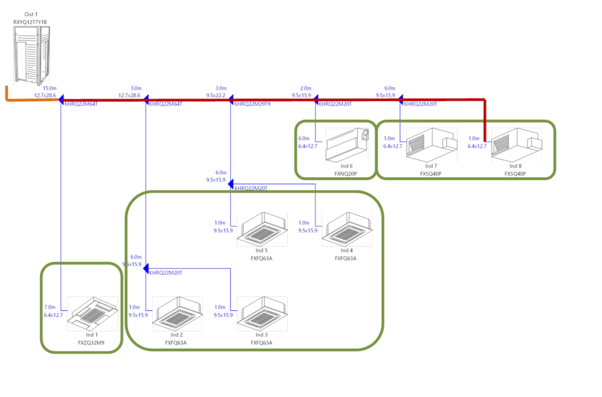
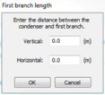
The above diagram shows 4 rooms with pipework going down a corridor and branching off to each area. The pipework distance from the condenser (outdoor) unit to the first branch in the refrigerant pipe network needs to be known as it clarifies the height difference which is set by right clicking the zone in the plugin that is the first branch from the main pipework from the condenser
On selecting this zone you enter the vertical and horizontal pipe length. In the above example the condenser is above the fan coils. If the condenser is below the fan coils then a negative number (in meters) would need to be input into the vertical box.
The other important pipework calculations are initially estimated by the plugin.
In order to maintain accuracy measured pipework lengths should be used by double clicking on the pipelength boxes in the VRV plugin display
At early design stages it is unlikely you’ll know the pipe route, so an estimation of the likeliest pipe lengths is acceptable to ascertain a system efficiency. When the pipe lengths are known then these can be added in at a later date to improve the accuracy of the simulation.
If you have any queries or require any assistance with pipe lengths or any other aspect of the VRV system design then please do not hesitate to contact Daikin at Engineering@Daikin.co.uk .