The effect of some common renewable technologies can be included in ApacheSim analysis for both dynamic thermal modelling and for VE Compliance analysis for Part L2. Available Electricity Generators are:
1 Photovoltaic (PV) panels
2 Wind generators
3 Combined heat and power (CHP)
Access the Electricity Generators from the ‘electricity’ icon on the toolbar.
PV Panels
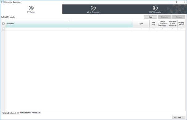
This dialog allows you to describe a photovoltaic system supplying electrical power to the building. Specify the existence of such a system by adding one or more entries to the list of PV panels.
There are two options: Freestanding Panels (see ModelIT User Guide) and Parametric Panels.
Parametric Panels: Defined PV panels data
Type
The user-defined type of the panel.
Area
The area of the panel (m²).
Azimuth
Panel azimuth angle in degrees clockwise from north.
Inclination
Panel tilt angle in degrees from horizontal.
Shading factor
If adjacent buildings or any other object shades the PV array, the average shading effect can be modelled by reducing the shading factor from the default value of 1.000 (1.0 not shaded 0.0 fully shaded).
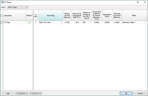
Parametric Panels: PV Types (previously PV array type and performance parameters)
Add new PV Types to the list and define the performance parameters.
Description
Enter a description for the PV Type.
Default?
Define which PV Type is the default. Selecting a type included in the table will populate the data grid on the right with the corresponding data relative to that type.
In Use?
This is linked to the ‘Defined PV Panels’ dialog. If a particular panel is selected from the ‘Type’ drop-down, it is defined as ‘In Use’
Technology Type
Choose a PV array type from the 6 options
· Amorphous silicon
· Monocrystalline silicon
· Other thin films
· Polycrystalline silicon
· Thin Film Cadmium-Telluride
· Thin Film Copper-Indium-Gallium-Diselenide
If you do not have specific data on the performance of the PV array you can tick this box to apply suitable defaults based on the PV array type.
PV array manufacturers then provide standard defaults, as standard.
Module Nominal Efficiency (η0)
The nominal efficiency is the fraction of solar radiant power that is converted to useful electrical power at a standard temperature and solar irradiance.
Nominal Cell Temperature (NOCT) (˚C)
The cell temperature under standard test conditions – ambient air temperature 20 ° C and irradiance either 800 or 1000 W/m2.
Reference Irradiance for NOCT (W/m²)
There is a degree of standardisation in the presentation of PV performance data. For example, there are Standard Test Conditions (STCs) for current, voltage, output power and temperature coefficient, and Standard Operating Conditions (SOCs) for NOCT. However, two standards are in use for SOCs, based on irradiances of 800 and 1000 W/m2 respectively, so one should always check the stated conditions.
Temperature Coefficient for Module efficiency (1/K)
This parameter describes the rate at which the panel’s conversion efficiency falls off with increasing cell temperature.
η = η0 [1 – β (Tc – Ta )]
where
η is the conversion efficiency at cell temperature Tc and outside temperature Ta
Adjustment factors
Degradation factor
Field measurements of a representative sample of PV modules may show that the PV module powers are different than the nameplate rating or that they experienced light-induced degradation upon exposure (even crystalline silicon PV modules typically lose 2% of their initial power before power stabilizes after the first few hours of exposure to sunlight). The degradation factor accounts for this drop in performance.
Electrical conversion efficiency
This is the combined efficiency of conversion of DC electrical power from the panel to delivered AC electrical power.
Meter
The Meter recording the power output.
Select the associated Electricity Meter from the drop down. Define Meters within ‘Energy Sources and Meters’.
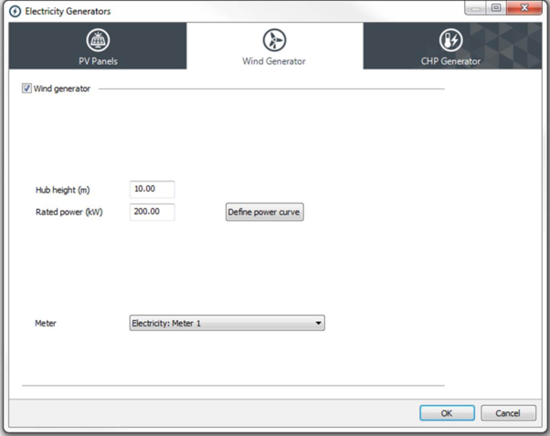
Wind Generator
This dialog allows you to describe a wind generator supplying electrical power to the building.
Wind generator parameters
· Wind generator
Tick this box to specify the existence of a wind generator.
· Hub height
The height of the turbine hub above the ground.
· Rated power
The maximum output power of the turbine.
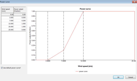
Power curve
Click on Define power curve to display the power curve parameters for editing.
You can use the default power curve or specify your own.
The power curve is defined as output power, here expressed as a fraction of rated power, as a function of wind speed. The first point on the power curve, which is uneditable, is (0,0). The second point indicates the cut-in wind speed – the wind speed at which the generator will start to generate power. The power output at this point is uneditable at the value zero.
Above a certain wind speed (the furling or governing speed) the turbine power output will be automatically limited in order to prevent damage to the machine. The best wind turbines will continue to deliver rated power in very high wind speeds, but many will shut down instead. The default power curve has a cut-off wind speed of 25 m/s, but wind speeds of this magnitude are rare.
The wind speed plotted on the power curve is the wind speed at hub height. This is calculated as a function of meteorological wind speed recorded on the weather file and the terrain type specified in APlocate.
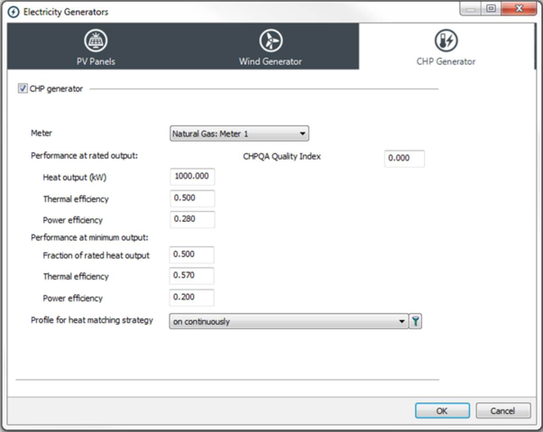
CHP Generator
This dialog allows you to describe a combined heat and power plant supplying heat and electrical power to the building.
As currently configured, the CHP system operates a heat matching strategy, attempting to provide the heating needs of the building while generating electricity as a by-product. The operation of the CHP plant is dependent on:
The enabling of the appropriate heating systems for CHP input.
The minimum and maximum power output of the CHP system.
The profile for heat matching.
Each heating system (Apache System, ApacheHVAC boiler or ApacheHVAC direct acting heater) must be enabled for CHP input if it is to receive heat from the CHP system. This is done by ticking the CHP box for the system in question. Next to the CHP box is a Boiler Ranking parameter which allows you to specify the order in which the boilers are switched on when the CHP system is either off or unable to meet the total heating load. Boilers with low Boiler Ranking will be switched on first. These will normally be the most efficient. Where two boilers have the same Boiler Ranking the CHP plant will contribute the same fraction of the heating load for both systems.
CHP availability and fuel
· CHP generator
Tick this box to specify the existence of a CHP system.
· Fuel type
The fuel burnt by the CHP system.
· Performance at rated output
The following properties define the performance of the generator at its rated output.
· Heat output
The maximum heat output
· Thermal efficiency
The thermal efficiency (heat output divided by energy content of fuel burnt) at rated output.
· Power efficiency
The power efficiency (power output divided by energy content of fuel burnt) at rated output.
· Performance at minimum output
The following properties define the performance of the generator at its minimum heat output.
· Heat output
The minimum heat output, expressed as a fraction of the rated heat output.
· Thermal efficiency
The thermal efficiency at the minimum heat output.
· Power efficiency
The power efficiency at the minimum heat output.
· Profiles
· Profile for heat matching strategy
Select a variation profile that defines the periods when the CHP system will attempt to match the heating load. The usual setting is ‘on continuously’.
· Profile for power matching strategy
This feature is not available in version 5.6. When enabled it will allow the CHP system to operate a power matching strategy and various combinations of heat-matching and power-matching.