Editing Multiplex (incl. Components & Controllers)
Multiplex Toolbar
The multiplex toolbar is active when any component or controller in a multiplex is selected.
Edit Multiplex
This second button on the Multiplex toolbar opens the Edit Multiplex dialog.
Edit Mode
Choose between Local or Global Editing.
Local Edit Mode – edits apply only to the current Display Layer.
Global Edit Mode – edits apply to all currently selected layers, as shown in the Create/Edit multiplex dialog and on the multiplex toolbar.
Display Layer
The currently active layer is displayed here. This can be identified by layer number and principal room. It is the layer that one can be altered in Local Edit mode and is the layer that will be viewed and serves as the Global Edit interface (prior to entering the Data Table edit view) when in Global Edit mode. Toggle through layers using the arrow buttons or expand the dropdown to select a layer from the list.
The current display layer can be changed while a room, component, or controller dialog is active, and the contents of that dialog will update to reflect the newly selected layer.
Edit Multiplex Dialog
When the Edit Multiplex button is clicked the Edit Multiplex dialog is displayed. This is used to add or remove layers, assign principal rooms, and select layers for editing in the same way as the Create Multiplex dialog described earlier.
Lock Layer Selection
When multiple layers are selected (selection must be set while in Global Edit mode) tick Lock Layer Selection to avoid accidentally editing an unselected layer. The locked state will apply to both Global and Local edit modes.
When cycling through layers on the multiplex toolbar while the selection is locked, a warning will be displayed if any locked layer is selected. The user has the option to unlock that layer or revert to the previously selected current display layer.
Editing Components and Controllers in multiplex
Once a multiplex has been created, the components and controllers within it can be edited in much the same way as those on any other part of the network.
Click once inside the multiplex region or on any component within it to make it active. This will update the toolbar with information regarding the current display layer, selection set, and editing mode for that multiplex. It is then possible to edit the components, controllers, and connectors within the multiplex much as is done outside a multiplex; however, edits are applied according to the layer selection set and edit mode. Select Local or Global Edit mode from the multiplex toolbar then edit properties of the network components.
Note: It is important to be aware when editing within a multiplex that, at least presently, changes cannot be undone.
Note: Because all layers must contain the same set of components, controllers, and connectors in the same layout (though not with the same settings, profiles, etc.), moving, copying, and deleting any item within the multiplex region must be done in Global Edit mode with all layers selected.
In Local edit mode the properties for the controller or component on the current Display layer are displayed and can be modified.
The properties displayed will be updated if a different Display Layer is selected from the multiplex toolbar via either the drop-down list or up/down arrows.
In Global edit mode, changes to controller or component parameters that are made in the normal (non-tabular-edit) dialog are applied to all layers in the current selection. Global edits apply more broadly in the case of Room Unit controllers (see next section below).
Tabular Editing
When in Global Edit mode, click the button containing the name or label for any variable input field in a component or controller dialog to use the tabular editing Data Table view to efficiently view and edit values on multiple layers (see the Tabular Editing section below for more information).
Touch Edits
When editing a controller or component in Global edit mode, double-clicking in any variable input field will update that variable in all other layers to match the value in the display layer. The variable input field will be colored orange to indicate that a Touch Edit has been completed. Clicking OK applies all Touch Edits made in the current dialog (these can be verified in the Data Table edit view). Canceling one or more Touch Edits in a component or controller dialog is done by Cancelling out of the dialog.
Edit Room Component Instances and Room Unit Controllers
Room Unit component instances (Radiators, Direct Acting Heaters, Chilled Ceilings) and their controllers, as located within multiplexed rooms, can be edited locally or globally. Room Unit controllers should generally be edited in Local Edit mode, except when replicating a controller and ALL of its settings. The list of room units in any given room is sorted first by Unit Type, with multiple instances of a Room Unit Type grouped together.
Global edits to room units within a multiplex apply to the currently selected room unit and those in other selected layers that are of the same type and position within the ordered list of units of that type (if such a room unit exists in the rooms on the other layers). Clicking OK in a Room Unit controller when in Global Edit mode will apply not only newly edited values but ALL inputs and settings in that dialog to all corresponding room unit controllers.
In the Room dialog, the column to the left of the room units description indicates the unit type for each particular room unit instance in that room. This type plays an important role: Whenever a room unit is selected for editing or deleting while in Global Edit mode, it is associated with corresponding room units in each of the other selected layers by means of its type and position within the ordered list of units of that type. For example, editing the second instance of radiator type ”Rad1_14-kW” in the principal room on the display layer would result in the edits being applied to the second radiator of type ”Rad1_14-kW” within the principal room on each currently selected layer in the multiplex.
Copying only modified parameters
As of version 6.3, only those parameters just modified on the display layer to be copied to the matching Room units (if any) in all selected layers when OK is clicked.
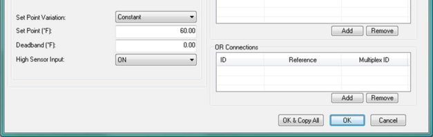
Figure 3 - 4 : In Global Edit mode there are two OK buttons for multiplexed Room unit controller dialogs, as shown here. OK & Copy All replicates the data in all the controller fields on the display layer to controllers for corresponding room units on other currently selected layers, whereas OK replicates only the data that has just been modified and not yet saved.
Tabular Editing
Tabular Editing allows input values for components and controllers on all layers to be reviewed or edited in a data table format. When in Global Edit mode with more than one layer currently selected, open the properties dialog of any controller or component then select the variable to be edited. This is not yet supported for Room Unit controllers.
Multiple Edit
To select multiple variables for tabular editing, hold the Shift key and select the desired variables; then click the “Multiple Edit” button. This opens a data table displaying the values for the selected parameter(s) and/or variable(s) of the component or controller on each selected layer.
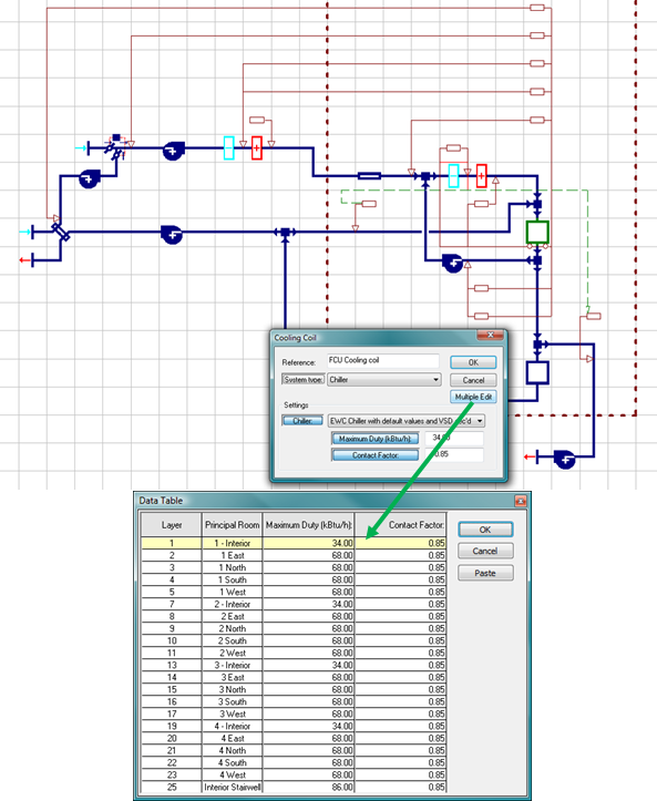
Figure 3 - 5 : Illustration of Multiple Edit function in the dialog of a multiplexed component or controller
Paste to Data Table using tabular edit view
Values from a spreadsheet or comma-separated value (CSV) file can be pasted directly into a Data Table column in tabular edit view. You can thus update unique values for a selected variable on multiple layers.
Select and copy source data from a column or row, then select the uppermost variable cell you would like to edit in the Data Table and click the Paste button to the right of the table. The paste will begin with the selected cell and continue downwards, entering new values on each layer up to the total number of values present in the copied selection set.
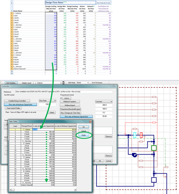
Figure 3 - 6 : Illustration of using copy & paste from a spreadsheet to tabular edit view
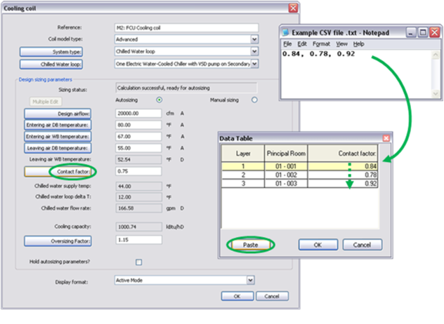
Figure 3 - 7 : Copy & paste from a CSV file to tabular edit view
Note: If the Paste is performed without first clicking on any cell in the Data Table, and multiple variables have been selected for inclusion in the Data Table view, the copied values will be assigned to the last variable column (at the right side of the table). The paste will begin with the current Display Layer (row highlighted in yellow) and continue downwards, entering new values on each layer up to the total number of values present in the copied selection set.
Note: It is possible to paste numeric or text characters. However, any pasted text must exactly match the available options for that input (e.g., Profile names must exactly match the names of available profiles in the ApPro database; Boiler names must exactly match those defined in the Heat Sources dialog; etc.).
Note: Tabular Editing of Room Unit controller parameters and input data is not yet supported. Room Unit controllers should be edited in Local Edit mode with just one exception: Use Global Edit mode when the intent is to apply ALL settings within a particular Room Unit controller to ALL other controllers for that unit Type within the currently selected Rooms.
Node Numbering
At the boundary of a multiplex an extra node number is generated. This is hidden, as it effectively includes both a node on the outside of the boundary (corresponding to the last labeled node outside the multiplex) and another node for each layer on the inside of the boundary, corresponding to the nearest labeled node on the inside. Together, these hidden nodes form a junction where the network branches into layers—i.e., from layer zero on the outside to each the numbered layers of the multiplex.
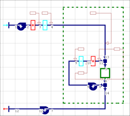
In the example below, the multiplex junction exists between nodes 4 and 13 and between nodes 14 and 7:
Figure 3 - 8 : Node numbering in a multiplexed system
Node numbers are not always sequential across multiplex boundaries. This is merely an artifact of how the multiplexed network is handled by the software, and may change in future versions.
As viewed either in Vista Results or in an error message, node numbers within a multiplexed ApacheHVAC network are numbered 1, 2, 3,… as in a normal network, but with the layer number appended to indicate the layer—e.g., the nodes on layer zero are 1/0, 2/0, 3/0, … and on layer 1 are 1/1, 2/1. 3/1, … and on layer 2 are 1/2, 2/2, 3/2,….and so forth.
Note: Some non-multiplexed nodes may be numbered 1/ , with layer zero being assumed. This is most likely to be seen in a message regarding insufficient flow definition, over-constrained flow, or similar.
Delete Multiplex
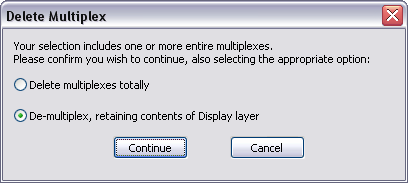
A multiplex can be “de-multiplexed” (collapsed to just the current display layer) or deleted by selecting any cell in the multiplex region on the network diagram then clicking the Delete button (trashcan) on the toolbar.
Figure 3 - 9 : When de-multiplexing or deleting a multiplex, a pop-up dialog requires a choice between deleting the entire multiplex and all items within it, or simply de-multiplexing.
Delete multiplex
The multiplex is removed and all components and controllers within the multiplex are completely deleted from the network.
De-multiplex
The multiplex is removed but the current Display Layer is retained in the network (on layer zero). This is the default action. Prior to de-multiplexing, check the currently selected layer if you intend to retain a layer containing a particular set of inputs to components and controllers.