Creating a Multiplex – Overview
A multiplex is created by selecting the Multiplex Add button in the main toolbar & dragging the green multiplex box from the bottom left to the top right corner of the desired multiplex region. Rules for multiplexes and multiplexed controllers are provided below, following the illustration of basic steps.
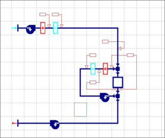
Step 1: Position the green multiplex box at the bottom left corner of the area of network that you wish to multiplex.
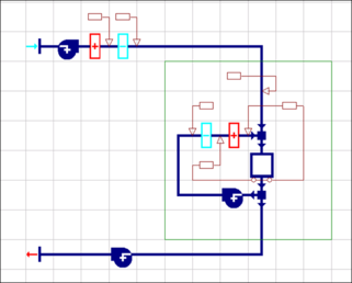
Step 2: Holding down the left mouse button drag the green multiplex box from the bottom left to the top right of the desired multiplex region and release the button.
Step 3: Once the rectangular boundary for the multiplex region of the system has been dragged over the network components, the Create Multiplex dialog will appear.
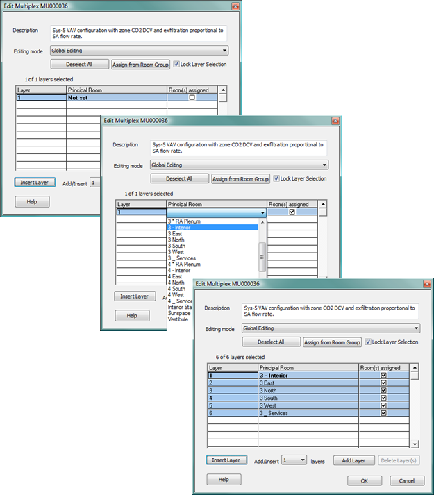
Rooms or thermal zones in the model are assigned to multiplex layers either by adding layers and manually selecting the spaces from the Principal Room drop-down list on each layer or by using the “Assign from Room Group” feature. These are described in more detail under Create Multiplex, below.
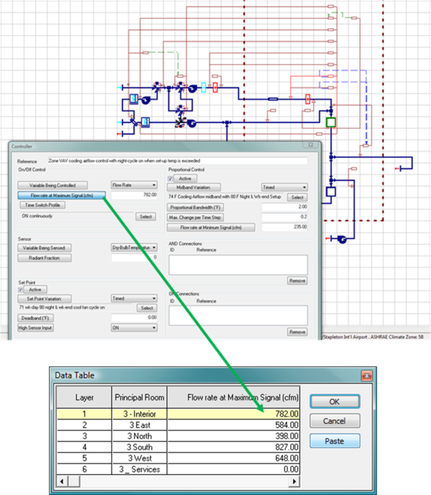
Step 4: Once a multiplex has been created, the network components and controllers can be populated with input values appropriate to the zones and desired control functions on each layer. Calculated flow rates, set points, cooling coil capacities, reference formula profiles, etc. can be entered into the network controllers layer by layer (Local editing), in all currently selected layers (Global editing), or pasted from a spreadsheet into a range of selected layers via a tabular Data Table edit view (Global editing). For autosizing of values within multiplexed components and controllers, see the System Prototypes & Sizing section of this User Guide.
Rules for Multiplexes and controllers within them
When defining the multiplex region, some rules must be followed:
· The multiplexed region of the network must contain at least one room component.
· A multiplex boundary must not abut or overlap an existing multiplex.
· It must satisfy the rules for controllers in a multiplex, as follows;
1. A controller is in a multiplex if its control box is inside the multiplex boundary.
2. Any controller outside a multiplex may only sense or control non-multiplexed nodes.
3. A controller inside a multiplex can sense and control any nodes inside or outside the multiplex.
4. A controller inside a multiplex may not sense and control nodes in another multiplex.
5. AND or OR connections cannot connect a controller in one multiplex to a controller in another multiplex.
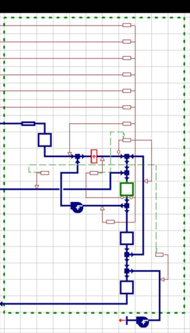
· A multiplex must not contain any sections of a network that consist only of connectors (see Figure 3-3 below).
·
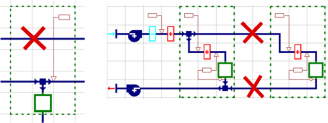
Figure 3 - 3 : Disallowed use of connector segments through a multiplex and between multiplexes
Any connection between multiplexes must contain at least one component or junction so that nodes can be generated (see Figure 6-3 below).
Figure 3-3 provides examples of network branches consisting solely of connecting segments that are not permitted within a multiplex. In cases such as that shown on the left, either re-route the connectors around the anticipated multiplex region or move the controller box downwards so that the multiplex with not overlap the upper path. Direct connections between multiplexes consisting solely of connecting segments (straight or elbow), such as illustrated on the right-hand side of this figure, are not permitted. The network must be revised so that there is a junction or other component between the multiplexes.
Note: It will be common to have multiple-layer instances of a controller pointing to one component control node. In such cases, the controller will “compete” for or “vote” on the value of the controlled variable at every simulation time step. The value that prevails depends upon the controlled variable and type of component being controlled. For example, while the highest temperature will prevail in the case of a heating coil, the lowest temperature will prevail for a cooling coil.
Warning: Where multiple airflow controls are present on one branch, these must all point to the same node if their operation will ever compete for control. An attempt to simultaneously control airflow from two different nodes on a single branch will result in an over-constrained flow.
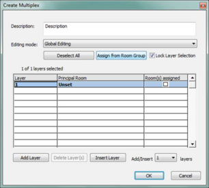
Create Multiplex
When a new multiplex is created by defining its boundary, the Create Multiplex dialog is displayed. The name and description of the multiplex, the number of layers contained in the multiplex, and the principal room assignment to each layer are entered here. See also section 3.2.5 3.2.5 Assign from Room Group below.
Description
Enter a name and description here to make it easier to identify the multiplex and manage complex systems.
Editing Mode
Edit parameters within components and controllers on one layer at a time (Local editing) or a selection of layers (Global editing).
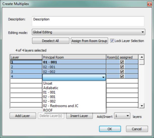
Layers
Assign from Room Group, as described the section dedicated to that below, is the most efficient way to add and populate the correct number of layers in a system multiplex. Alternatively, simply select the number of layers to be added to or inserted into the multiplex, then click Insert Layer (new layers are inserted at the selected layer) or Add Layer (layers are appended to the bottom of the list).
Select layers then click Delete Layers to remove them from the list (note it is not possible to delete all layers from a multiplex)
The Ctrl and Shift keys are used to add or remove individual layers to or from the current selection set and to hold the view from scrolling when there are more layers than can be viewed at once.
Lock Layer Selection
When multiple layers are selected (selection must be set while in Global Edit mode) tick Lock Layer Selection to avoid accidentally editing an unselected layer—e.g., after switching layers on the toolbar. The locked state applies to both Global and Local edit modes.
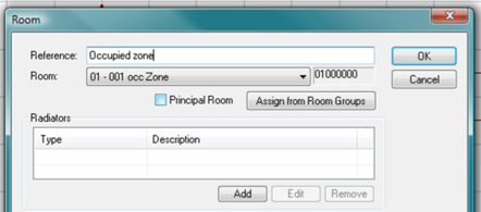
Principal Rooms
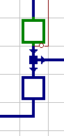
The first room in the multiplex network is nominated as the Principal Room and indicated as a green room component on the network.
Each layer in the multiplex is assigned a Principal Room to help identify the layer. Double click the Principal Room column for any Layer to select the Principal room from the list of rooms in the model.
Each layer in a multiplex can have more than one Room component on it. All layers, however, must include the same number of Room components. Three examples of this are provided below.
Room components can have duplicate assignments across multiple layers. This is most typically used for non-principal rooms (see examples 1 and 3 below).
Non-principal room components can remain unused on selected layers. This requires only that they are set via their Room assignment to act as an “Adiabatic duct,” rather than being associated with a room or zone in the 3D model (see examples 1 and 2 below).
To change a room component on the network from a non-principal room (blue outline) for all layers to the Principal Room for all layers, double-click the desired room component and then tick the box next to Principal Room within the Room dialog. As this is equivalent to adding or deleting a component, the determination of the component that is the Principal Room must be consistent across all layers in a multiplex.
When including more than one room component on each multiplex layer, the principal Room is typically the occupied space with which a thermostat or other sensors and controls are associated.
Example 1: It is common to have a return air (RA) plenum void in commercial spaces. This should be modeled as a separate thermal zone over top of all of the zones it serves. There may, for example, be one plenum for each floor of the building. These RA plenums would be represented by a non-principal “room” component directly downstream of the occupied space on all multiplex layers. However, the Principal Room component on each layer will typically be assigned a different space in the model. Therefore, if there were one RA plenum for entire 1st floor, it would need to be associated with all occupied thermal zones on that floor, and thus the same RA plenum space in the model should be assigned to the plenum room components on each of the layers that contain a room on the first floor that has a return-air grill.
If there are spaces on the first floor in this example that have supply air and either a ducted return or no return (perhaps they are exhausted), they would not be coupled with the RA plenum. For layers assigned to these spaces, the RA plenum component should be set as an Adiabatic duct.
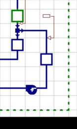
Example 2: There may be a principal room that contains a thermostat (sensors and controllers) and an adjacent room, such as a lavatory, that draws transfer air from the principal room and has no thermostat or other sensors associated with it. There must, however, be means of determining the airflow through it, even if the flow is intentionally set to zero. Typically, such rooms will have a path to either an exhaust fan or a return fan. This will draw air from an adjacent space, as in the lavatory in the illustration to the right.
As it is very unlikely that there would be a lavatory or similar space drawing transfer air adjacent to the Principal Room on every layer, this non-principal room component would be set as an Adiabatic duct on all layers for which it is to remain unused.
Example 3: In the case of an underfloor air distribution (UFAD) system, each layer would typically include the UFAD supply plenum, an occupied zone, a stratified zone, and possibly also a return-air (RA) plenum. The occupied spaces would normally be the Principal Room on each layer. As the UFAD plenum would be before this on the network, the component representing the occupied zone on the network would need to be changed from a non-principal room to the Principal Room for all layers, as described above.
As with the RA plenum in Example 1, each UFAD supply plenum serving more than one zone would be assigned to the designated UFAD plenum component on more multiple layers (the same layers as the occupied zones it serves).
For occupied zones served by the UFAD plenum, there would be a corresponding stratified zone assigned to a non-principal room component downstream of the Principal Room. If there is an RA plenum, this would be yet another non-principal room downstream of the stratified zone.
If there are spaces receiving supply air from the same airside system but not via the UFAD plenum, the UFAD plenum would be set to Adiabatic on those layers. Similarly, if those or other spaces were to be fully mixed zones using overhead diffusers, the stratified zone room component would be set to Adiabatic on those layers.
Assign from Room Group
The Assign from Room Group tool can be used to assign rooms to selected layers. It can also be used to automatically add layers to the multiplex for each room in a selected room group—i.e., to create exactly the number of additional layers that will be required for all rooms or thermal zones in the group.
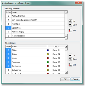
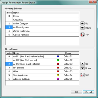
When in Global Editing mode, click the Assign from Room Group button. This opens the Assign from Room Group dialog showing the Grouping Schemes in the project.
Select a Grouping Scheme and Room Group then click the OK button to assign each room or thermal zone in the selected Group as a Principal Room on a multiplex layer. Hold the Ctrl key and click the Index numbers to select and thus simultaneously assign rooms from multiple Room Groups.
If there are more rooms in the group than layers in the multiplex, the option is given to create layers for each additional room. This is an efficient way to add layers.
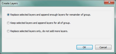
Create Layers dialog: Click the first option to replace currently selected layers and add any additional layers required to accommodate the full set of rooms in the group being assigned. Click the second option to add the required number of layers for the group, without replacing any of the existing multiplex layers. This is an efficient way to add layers to a multiplex. Click the third option to assign the rooms from the group to just the existing layers in the multiplex.
When the OK button is clicked to complete multiplex creation, the Editing mode and layer selection will be reflected in the multiplex toolbar and subsequent edits.
Room(s) assigned – The column of check boxes at the right-hand side of the Create/Edit Multiplex dialog indicates whether or not all Room components on a given multiplex layer have been assigned. The check boxes are not user-editable, but will include a check mark when assignments are complete for a layer. Assigning an Adiabatic duct rather than an actual space in the model to a Room component does count as an assignment.