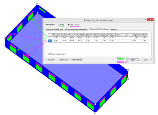
Edit Glazing, Doors Louvres
Edit Glazing, Doors and Louvres
(“Draw” Þ ”Openings” Þ “Edit Openings”)
Use this option to place, replace or remove glazing, doors or louvres in selected spaces.
:
There are four options:
· "Add by Percentage Area"
· "Add by Percentage Area /Heights"
· "Add by Height/Width/Spacing"
· "Remove"
Each tab has a different set of items to set:
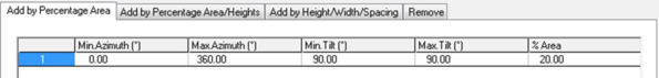
Add by Percentage Area
You can set the minimum and maximum azimuth in the first two columns and the minimum and maximum tilt in the third and fourth columns. For this tab the only other value to set is the "% Area".
At MODEL level - select a set of spaces - key in "g=50" (or "G=50") - this will create 50% glazing on external surfaces.
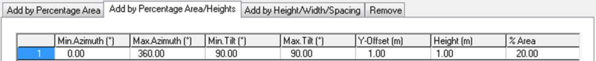
Add by Percentage Area /Heights
"Min. Azimuth", "Max Azimuth", "Min Tilt" and "Max Tilt" defined as above. The other values to set in this tab are the lower sill (Y-Offset) of the window, Height and "% Area".
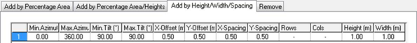
Add by Height/Width/Spacing
This tab allows a more complex arrangement to be defined:
"Min. Azimuth", "Max Azimuth", "Min Tilt" and "Max Tilt" defined as above. The distance from the edge of the wall is defined, "X-Offset", and from the bottom of the wall, "Y-Offset". The size of each window is defined by "Height" and "Width". The distance between each window is defined by "X-Spacing" and "Y-Spacing". The default is for the number of rows and columns to be automatically created by the numbers that fit, "-", but if required these may be constrained to a specific number.
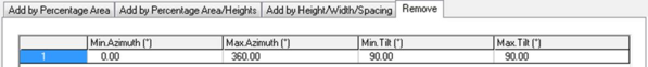
Remove
"Min. Azimuth", "Max Azimuth", "Min Tilt" and "Max Tilt" defined as above.
Click on "Apply" to apply the settings to the selected space(s).
Note: when entering azimuth or tilt angles, if you enter a minimum value that is greater than a maximum value or vice versa, the value that you last entered will reset itself.
Edit Opening size and shape
When in Surface level (see Model Decomposition), this function becomes active.
This feature allows to resized and reshape existing openings. Just left select a vertice and use the right mouse button to drag it to a new location. An arrow will show the vertex shift.