Manually Extrude Rooms/Zones
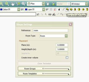
Click the ‘draw extruded shape’ button and the ‘shape settings’ window will open. Set the height of the room and what plane the room sits on. You can name the room here or you can choose to name the room later by right clicking on it in the room list in the side bar. Draw the outline of a room by clicking on points in the model view window to define the room vertices. It is important to snap to the grid.
Figure 16 - Shape Settings Dialog for drawing shapes
Import DXF & Manually Extrude
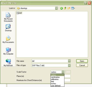
When importing a dxf it is important to select the correct scale factor. The drawing will appear in grey in the model view window and will sit behind the model. Use this to as a guide in which to trace your rooms over while snapping to the grid at all times.
Figure 17 - Attach DXF file dialog
Import GBXML (Revit, ArchuCAD etc)
This hyperlink offers an alternative to manually building a model within the <VE> ModelIT module. It allows a .GBXML file to be imported from another CAD platform such as ArchiCAD or other.
Note: IES has developed plug-ins (can be downloaded at
www.iesve.com ) for the following BIM platforms that facilitate translating the model into the VE platform in enhanced ways compared to straight GBXML:
· SketchUp and SketchUp Pro (version 6 & 7)
· Revit Architecture – 2009, 2010, 2011
· Revit MEP – 2008, 2009, 2010, 2011
Model Settings
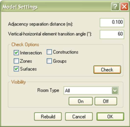
The model setting window allows you to change the adjacency separation distance, vertical-horizontal element transition angle and perform model checks.
Vertical-Horizontal Element Transition angle define at what angle a wall becomes a ceiling or a floor. By default, if a surface is at an angle less than 60o it is recognized by the software as a ceiling or floor.
Figure 18 - Model Settings Dialog Box
The model check option allows you to perform a check on the quality/integrity of the geometry in your model. Check the boxes for intersections and surfaces and click the check button. A text file will be created which will flag up any error in your model geometry. It is recommended to perform model check regularly throughout the model building process. It is usually far easier to fix a geometry problem soon after it occurs rather than at the end.
Clicking the rebuild button refreshes all the adjacencies in the model.