Direct Acting Heater/Cooler Control
Direct-acting heater/coolers can be used to directly add or subtract heat to/from a space as might be appropriate for a simple self-contained space heating or cooling device, such as an electric-resistance heater. It might also be used to model a solar heater directly coupled to an outdoor collector panel or a piece of non-HVAC equipment with significant thermal influence. The controller for the Direct acting heater/cooler is somewhat simpler than for Radiators and Chilled ceilings, as there is no water temperature or flow rate to control—just heat or “coolth” output.
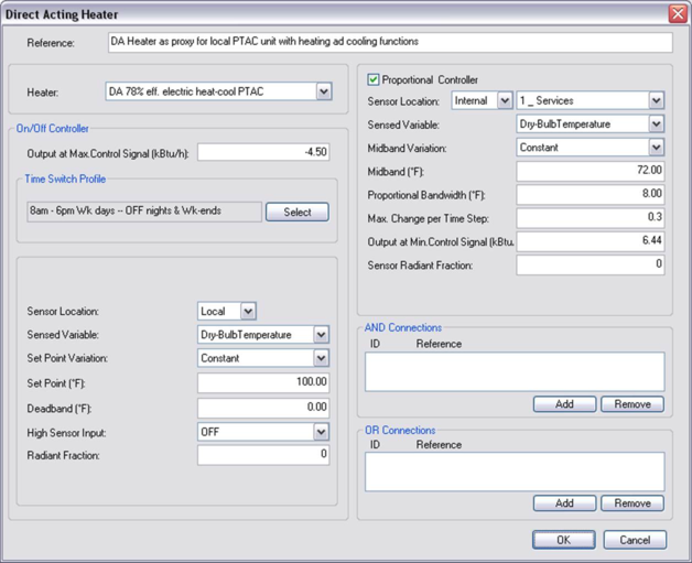
Figure 7 - 4 : Direct-acting heater/cooler control with illustrative inputs.
The illustrative inputs in the Direct-acting heater/cooler control in Figure 7-4 proportional provide both heating and cooling at opposite ends of a continuous control band (heating operation at Min signal and gradual transition to cooling operation at Max signal). In this example, Set point control is effectively forced to ON by using High-sensor = Off and a very high value for the set point. Thus the Time Switch schedule and the Proportional Control can fully determine the operation.
Settings
Reference
Enter a description of the controller. The reference is limited to 100 characters. It is for your use when selecting, organizing, and referencing any component or controllers within other component and controller dialogs and in the component browser tree. These references can be valuable in organizing and navigating the system and when the system model is later re-used on another project or passed on to another modeler. Reference names should thus be informative with respect to differentiating similar equipment, components, and controllers.
Heater (cooler)
Select the reference of a previously defined direct acting heater/cooler type for placement in the room from the direct acting heaters list.
On/off and set point controls
Output (heating or cooling effect) at Maximum Control Signal
Enter the heat (or cooling, as a negative value) output that corresponds to the maximum control signal from the controller. Note that for direct acting proportional control this value is greater than that in the ‘Output at minimum control signal' field, and for reverse acting it is smaller.
Time switch profile
Specify the time switch profile that will be used to schedule the operation of the controller.
Sensor location
The sensor may be internal (contained in a room or on a surface in a room) or external. An external sensor would be the equivalent of a weather compensated system or outdoor temperature reset. Several direct-acting heater/coolers may use the same internal sensor—e.g., heater/coolers in all rooms on the west façade of a building or all radiant slab zones associated with a larger space may be controlled by a single sensor. As would be appropriate for a hydronic loop in a conditioned slab, one surface temperature sensor per zone is available for use with on/off or proportional controls. The surface vs. zone location of the sensor is determined by selection of the sensed variable and tagging of the sensed surface within the Apache Thermal view. For more information on using surface temperature sensors, see section 6.3.2 Sensed variables.
Select an appropriate sensor location.
Sensed variable
Select the variable that is to be used in the on/off (set point) control.
Radiant fraction
When the sensed variable is dry-bulb temperature, an input field is available to set the radiant fraction of sensed temperature. As an example, if the radiant fraction were set to 0.5, the sensor would effectively be sensing dry resultant temperature—i.e., operative temperature in still air conditions.
Enter an appropriate value for a radiant fraction.
Set point variation
The set point for on/off control may be Constant or Variable. Select Constant or Timed as appropriate
Set point or variation profile
Enter a fixed setpoint value when the setpoint is Constant or select a timed profile when the setpoint variation is timed. This can be a formula profile.
Deadband
Deadband defines the controller hysteresis or range of sensed variable values over which switching occurs in on/off control (see section 6.6.3.4 ).
Enter an appropriate deadband value.
High sensor input (resulting on/off action)
This parameter relates to on/off (set point) control and specifies whether the switching signal output by the controller is ON or OFF for high values of the sensed variable. (See section 6.6.3.5 ).
Proportional control for heating and/or cooling output
Proportional control of output can be used, depending upon the values entered, to control heating effect, cooling effect, or both of these at opposing ends of c continuum.
Proportional Controller
Tick the box next to this item to use proportional control of the output. If proportional control is not used, the output will be fixed at the value set in the “Output at Max Control Signal” field.
Sensor location
The sensor may be internal (contained in a room or on a surface in a room) or external. An external sensor would be the equivalent of a weather compensated system or outdoor temperature reset. Several radiators may use the same internal sensor—e.g., all rooms on the west façade of a building may be controlled by a single sensor. As would be appropriate for a hydronic loop in a conditioned slab, one surface temperature sensor per zone is available for use with on/off or proportional controls. The surface vs. zone location of the sensor is determined by selection of the sensed variable and tagging of the sensed surface within the Apache Thermal view. For more information on using surface temperature sensors, see section 6.3.2 Sensed variables.
Sensed variable
Select the variable that is to be fed into the proportional control.
Surface temperature is available as a sensed variable for use with on/off or proportional controls, as would be appropriate for a hydronic loop in a conditioned slab. The surface vs. zone location of the sensor is determined by selection of the sensed variable. The specific surface adjacency for the sensor location must also be tagged within the Apache Thermal view. For more information on using surface temperature sensors, see section 6.3.2 Sensed variables.
Note: While Flow rate is on the Room Unit controller selection list of Sensed variables and does cause gpm or l/s units to be displayed, this sensed variable is not yet available for Room Unit controllers.
Midband variation
The midband for proportional control may be constant or variable—i.e., timed, scheduled, or determined by a formula profile (see section 6.6.4.2 ). Select Constant or Timed as appropriate.
Midband or variation profile
Enter a fixed midband value if Constant or select an appropriate midband variation profile if the variation is timed (see section 6.6.4.3 ).
Proportional bandwidth
The proportional bandwidth is the range of the sensed variable over which the proportional control will vary as bounded by maximum and minimum sensed values. This proportional bandwidth is centered about the midband (see section 6.6.4.4 ). Enter the bandwidth as appropriate.
Maximum change per time step
This parameter specifies the maximum fractional change that the controller can carry out in each simulation time step. The fraction is with respect to the overall range of control between the value at Max signal and the value at Min signal (see section 6.6.4.5 ).
Enter a value as needed to maintain stable operation of the unit. This must be complete for Proportional Flow and Temperature controllers when they are used. A good starting point is 0.2 to 0.3. If operation is unstable, reduce this value as needed—e.g., to 0.1 or 0.05.
Output at Minimum Control Signal
When proportional control is used, enter the output (heating as a positive value or cooling as a negative value) that corresponds to the minimum signal from the proportional controller. If no proportional control is specified, the value entered here will be ignored. The minimum control signal is generated when the sensed value is at or below the midband minus half the proportional band.
Radiant fraction (for sensor)
When the sensed variable is dry-bulb temperature, an input field is available to set the radiant fraction of temperature sensor. As an example, if the radiant fraction were set to 0.5, the sensor would effectively be sensing dry resultant temperature—i.e., operative temperature in still air conditions.
Orientation
When the sensed variable is Solar radiation, enter the orientation or azimuth of the sensing surface in degrees (0 deg = North and 180 deg = South).
Slope
When the sensed variable is Solar radiation, enter the slope (angle from horizontal) of the surface containing the sensor in degrees (0 deg = horizontal and 90 deg = vertical)
AND References
Add/Remove logical AND connections to other controllers as appropriate (see section 6.6.5 ).
OR Reference
Add/Remove logical OR connections to other controllers as appropriate (see section 6.6.6 ).