In ApacheHVAC, the term “Chilled ceilings” covers a range of hydronic cooling devices placed directly in conditioned spaces. These include flat chilled panels with primarily radiant cooling effect and perforated or convoluted panels with largely convective cooling effect—e.g., “passive chilled beams” (active chilled beams, which are truly induction units, are modeled as such on the airside network, and pre-defined systems are provided for this). Chilled Ceiling types can also be used as a hydronic loop within a chilled slab zone; however, care should be taken in such cases to appropriately define the “type” using parameters that will represent the properties of just the hydronic loop within the slab.
Local-thermostatically controlled units, control by sensors in other locations, control by surface temperature sensors, and controlled variable water flow rates and temperature can be modeled using a versatile combination of On/Off and Proportional controllers. Six different sensed variables are available as direct input to controllers. Logical AND and OR connections to other controllers as well as formula profiles can be used to account for other sensed outdoor and HVAC system variables.
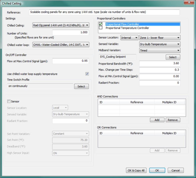
Figure 7 - 3 : Chilled Ceiling control dialog with illustrative inputs for water flow rate, coupling to chilled-water loop supply temperature, and referencing a cooling panel type than can readily be scaled with respect to the number of units required in each zone.
Reference name
Enter a descriptive name for the controller. The reference is limited to 100 characters. It is for your use when selecting, organizing, and referencing any component or controllers within other component and controller dialogs. These references can be valuable in organizing and navigating the system and when the system model is later re-used on another project or passed on to another modeler. Reference names should thus be informative with respect to differentiating similar equipment, components, and controllers.
Settings
Chilled Ceiling Type Reference
Select a chilled ceiling device for placement in the room from the list of previously defined types.
Number of units
Enter the number of copies of this chilled ceiling panel type to be included within the associated space. This can be any number between 0 and 1,000, including non-integer values and values less than 1.0, but excluding 0. This parameter provides for the scaling of a defined room unit type as applied to spaces with differing loads. For example, a Chilled ceiling panel type with 1.0 kW cooling output at design conditions can be defined as a type, and a room or thermal zone requiring 14.5 kW of radiant + convective cooling from the panels at design conditions can use 14.5 units of this type.
Chiller
Select the chilled water loop that will serve the chilled ceiling device.
On/off and set point controls
Flow for Maximum Control Signal
Enter the flow rate that corresponds to the maximum control signal from the controller. If no proportional control is to be used, enter the flow rate that occurs whenever this chilled ceiling device is on. Note that for direct acting proportional control where the sensed variable is room temperature (typical for a cooling device), this value is higher than that in the water temperature at minimum control signal, and for reverse-acting control, it is lower.
|
Warning Limits (l/s)
|
0.001 to 2.5
|
|
Error Limits (l/s)
|
0.0 to 99.0
|
Chilled Ceiling Water Temperature for Maximum Control Signal
Enter the water temperature that corresponds to the maximum control signal from the proportional controller. If no proportional controller was specified, enter the temperature of the chilled ceiling supply water. Note that for direct acting proportional control where the sensed variable is room temperature (typical for a cooling device), this value is higher than that in the water temperature at minimum control signal, and for reverse-acting control, it is lower. This parameter is not used when “Use chilled water loop supply temperature?” is checked.
Use chilled water loop supply temperature
Selecting this option sets the water temperature entering the radiant cooling panel or passive chilled beam to the supply temperature of the connected chilled water loop. The panel or beam will therefore see any change in chilled water supply temperature resulting from supply temperature reset controls or off-design supply temperatures resulting from an undersized chiller or similar capacity limitation.
This option is available only when the chilled ceiling has proportional flow control enabled and is served by a chilled water loop. It is not available with proportional temperature control, which would be used in lieu of this option for the purpose of modeling a zone-level mixing valve capable of locally modulating the water temperature supplied to this cooling device.
Time switch profile
Specify the time switch profile that will be used to schedule the operation of the controller.
Sensor location
The sensor may be internal (contained in a room or on a surface in a room) or external. An external sensor would be the equivalent of a weather compensated system or outdoor temperature reset. Several chilled ceiling panel arrays may use the same internal sensor—e.g., chilled ceilings in all rooms on the west façade of a building may be controlled by a single sensor. As would be appropriate for a hydronic loop in a conditioned slab, one surface temperature sensor per zone is available for use with on/off or proportional controls. The surface vs. zone location of the sensor is determined by selection of the sensed variable and tagging of the sensed surface within the Apache Thermal view. For more information on using surface temperature sensors, see section 6.3.2 Sensed variables.
Select an appropriate sensor location.
Sensed variable
Select the variable that is to be used in the on/off (set point) control.
Surface temperature is available as a sensed variable for use with on/off or proportional controls, as would be appropriate for a hydronic loop in a conditioned slab. The surface vs. zone location of the sensor is determined by selection of the sensed variable. The specific surface adjacency for the sensor location must also be tagged within the Apache Thermal view. For more information on using surface temperature sensors, see section 6.3.2 Sensed variables.
Note: While Flow rate is on the Room Unit controller selection list of Sensed variables and does cause gpm or l/s units to be displayed, this sensed variable is not yet available for Room Unit controllers.
Radiant fraction
When the sensed variable is dry-bulb temperature, an input field is available to set the radiant fraction of sensed temperature. As an example, if the radiant fraction were set to 0.5, the sensor would effectively be sensing dry resultant temperature—i.e., operative temperature in still air conditions.
Enter an appropriate value for a radiant fraction.
Set point variation
The set point for on/off control may be Constant or Variable. Select Constant or Timed as appropriate
Set point or variation profile
Enter a fixed setpoint value when the setpoint is Constant or select a timed profile when the setpoint variation is timed. This can be a formula profile.
Deadband
Deadband defines the controller hysteresis or range of sensed variable values over which switching occurs in on/off control (see section 6.6.3.4 ).
Enter an appropriate deadband value.
High sensor input (resulting on/off action)
This parameter relates to on/off (set point) control and specifies whether the switching signal output by the controller is ON or OFF for high values of the sensed variable. (See section 6.6.3.5 ).
Enter the appropriate sensor input.
Proportional controls for water flow rate and temperature
Both proportional flow and temperature controls are provided. To minimize redundant explanations, however, the inputs that are identical for these two types of proportional control will be described just once in the following subsections.
Proportional Flow Controller
Tick the box next to this item to use proportional control of the water flow rate in the chilled ceiling (panel, hydronic loop, etc.). Then click on the item to enter and edit parameters for the proportional controller. If proportional control of water flow rate is not used, the water flow rate will be fixed at the value given in the “Flow at Max Control Signal” input.
Proportional Temperature Controller
Tick the box next to this item to use proportional control of the water temperature in the chilled ceiling (panel, hydronic loop, etc.). Then click on the item to enter and edit parameters for the proportional controller. If proportional control of water temperature is not used, the water temperature will be fixed at the value given in the “Temp at Max Control Signal” input.
Sensor location
The sensor may be internal (contained in a room or on a surface in a room) or external. An external sensor would be the equivalent of a weather compensated system or outdoor temperature reset. Several chilled ceiling panel arrays or radiant slabs may use the same internal sensor—e.g., chilled surfaces in all rooms on the west façade of a building may be controlled by a single sensor. As would be appropriate for a hydronic loop in a conditioned slab, one surface temperature sensor per zone is available for use with on/off or proportional controls. The surface vs. zone location of the sensor is determined by selection of the sensed variable and tagging of the sensed surface within the Apache Thermal view. For more information on using surface temperature sensors, see section 6.3.2 Sensed variables.
Select an appropriate sensor location. This must be done separately for both Proportional Flow and Temperature controllers when they are included.
Sensed variable
Select the variable that is to be used in the proportional control. This must be done separately for both Proportional Flow and Temperature controllers when they are included.
Surface temperature is available as a sensed variable for use with on/off or proportional controls, as would be appropriate for a hydronic loop in a conditioned slab. The surface vs. zone location of the sensor is determined by selection of the sensed variable. The specific surface adjacency for the sensor location must also be tagged within the Apache Thermal view. For more information on using surface temperature sensors, see section 6.3.2 Sensed variables.
Note: While Flow rate is on the Room Unit controller selection list of Sensed variables and does cause gpm or l/s units to be displayed, this sensed variable is not yet available for Room Unit controllers.
Midband variation
The midband for proportional control may be constant or variable—i.e., timed, scheduled, or determined by a formula profile (see section 6.6.4.2 ). Select Constant or Timed as appropriate. This must be completed for Proportional Flow and Temperature controllers when they are used.
Midband or variation profile
Enter a fixed midband value if Constant or select an appropriate midband variation profile if the variation is timed (see section 6.6.4.3 ). This must be completed for Proportional Flow and Temperature controllers when they are used.
Proportional bandwidth
The proportional bandwidth is the range of the sensed variable over which the proportional control will vary as bounded by maximum and minimum sensed values. This proportional bandwidth is centered about the midband (see section 6.6.4.4 ). Enter the bandwidth as appropriate. This must be completed for Proportional Flow and Temperature controllers when they are used.
Maximum change per time step
This parameter specifies the maximum fractional change that the controller can carry out in each simulation time step. The fraction is with respect to the overall range of control between the value at Max signal and the value at Min signal (see section 6.6.4.5 ).
Enter a value as needed to maintain stable operation of the unit. This must be complete for Proportional Flow and Temperature controllers when they are used. A good starting point is 0.2 to 0.3. If operation is unstable, reduce this value as needed—e.g., to 0.1 or 0.05.
Flow at Minimum Control Signal
When proportional Flow control is used, enter the water flow rate that corresponds to the minimum signal from the proportional controller. If no proportional Flow controller is specified, the value entered here will be ignored. The minimum control signal is generated when the sensed value is at or below the midband minus half the proportional band.
Temperature at Minimum Control Signal
When proportional Temperature control is used, enter the water temperature that corresponds to the minimum signal from the proportional controller. If no proportional controller was specified, the value entered here will be ignored. Note that the minimum control signal is generated when the sensed value is at or below the midband minus half the proportional band.
Radiant fraction (for sensor)
When the sensed variable is dry-bulb temperature, an input field is available to set the radiant fraction of temperature sensor. As an example, if the radiant fraction were set to 0.5, the sensor would effectively be sensing dry resultant temperature—i.e., operative temperature in still air conditions.
Orientation
When the sensed variable is Solar radiation, enter the orientation or azimuth sensing surface in degrees (0 deg = North and 180 deg = South).
Slope
When the sensed variable is Solar radiation, enter the slope (angle from horizontal) of the surface containing the sensor in degrees (0 deg = horizontal and 90 deg = vertical)
AND References
Add/Remove logical AND connections to other controllers as appropriate (see section 6.6.5 ).
OR Reference
Add/Remove logical OR connections to other controllers as appropriate (see section 6.6.6 ).