Differences for Section 6 (2010)
Building & System Data
Tab: General
SBEM method
Certifier is renamed to Agent and the only details required are Name and contact details.
SBEM-EPC method
Certifier (L2) is renamed to Qualified Accredited Person.
Accreditation scheme (L2) is renamed to Protocol organisation and needs to be selected by the user, as it is not automatically linked to the entered Membership number, as is the case for accreditation schemes in Part L2.
No insurance details are required.
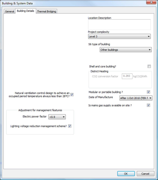
Tab: Building Details
The following Section 6 (2007) items have been dropped for both SBEM methods:
· Building air permeability at 50 Pa
· Related party disclosure
· Main heating fuel
· Ground floor U-values corrected in accordance with EN ISO 13370?
· Accredited Construction Details
SBEM Compliance method
In the SBEM Compliance method he following items, shown in the figure below, are different from Part L2 (2010):
· S6 type of building
· Natural ventilation control design to achieve an occupied period temperature always less than 28degC?
· Main renewable source
· Is mains gas supply available on site?
· (Adjustment for management features) Lighting voltage reduction management scheme?
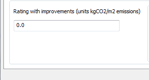
SBEM-EPC method
The following items are different from Part L2 (2010):
· The items listed in 2.1.2.1 above (SBEM method)
· Rating with improvements (kgCO2/m2 emissions)
The “Rating with improvements” will appear on the EPC as the second benchmark
figure, with the title “Where the accompanying recommendations for the cost effective
improvements are applied”.
Weather location (SBEMlocate)
Under Section 6 (2010) the weather location is required to be Glasgow, therefore
SBEMlocate is disabled.
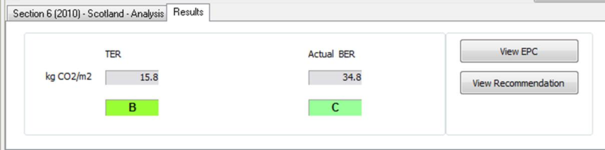
Results tab
SBEM-EPC method
Unlike the Part L2 and Part F EPC’s there is no “Rating” system, and there are only
two bands, based on the Actual and Target emission figures.
Calculation Differences
|
|
Section6 (2010)
|
PartL2 (2010)
|
|
Notional Building Construction U-values
|
|
Exposed Wall U-value
|
U=0.30
|
U=0.35
|
|
Pitched Roof U-value
|
U=0.16
|
Not specified
|
|
Notional building % glazing
|
|
Glazing for "Industrial and storage buildings"
|
15%
|
10%
|
|
BER calculation
|
|
Lighting Metering And Warning
|
Not used
|
If there is metering and warning of out-of-range values: Fl = 0.95, otherwise Fl=1.0
|
|
BER Calculation (see below for details)
|
(1.0f-Fnvca*(1.0f-Fnv)) * (Cst - (1.0f-Fe)*Cse + Fe*Flvrms*Clt);
|
Cst -((1-Fe)*Cse)+(Fe*Fl*Clt);
|
|
“Curtain Walls”
|
|
|
"In Section 6, unlike Part L, curtain walls are treated the same as ordinary walls."
|
Curtain Walls differentiated
|
|
U-value Limits
|
|
Walls - L1, L2
|
0.30
|
0.35
|
|
High-usage entrance doors
|
2.2
NO EXCEPTION HERE, so same as Personnel doors
|
6.0
|
2.4.1. BER Calculation Differences
Part L2
First, to explain the L2 adjustment, it's clearest to write the expression like this:
BER = Cst - Cse + Fe*Cse + Fe*Fl*Clt
where
Cst is the total uncorrected system carbon emissions (which doesn't include lights).
Cse is the portion of Cst which is attributable to electricity, and which is subject to a
correction. We first subtract off this portion from Cst ('- Cse'), then add back the
corrected version ('+ Fe*Cse').
Fe is the adjustment factor corresponding to the “Electric Power Factor” selected from the dialog (“Adjustment for management features” section).
Clt is the lights carbon emissions (always electrical), which is separate from Cst.
This has two correction factors applied: one because it's electrical (Fe) and one
because it's lights (Fl) (see “Adjustment for management features” section).
Section 6
The Section 6 correction applies to a certain fraction of the total carbon emissions,
after these have been adjusted with the corrections described above. If the result of
the above sum is:
BER1 = Cst - (1-Fe)*Cse + Fe*Flvrms*Clt
(where the Section 6 factor Flvrms "Lighting voltage reduction management scheme" replaces Fl) then the result of this second correction is
BER = (1-fraction)*BER1 + Fnv*fraction*BER1
where
the first term is the portion of BER1 that's not subject to correction, and the
second term is the portion of BER1 that is subject to correction, with the correction
applied.
Fnv = 0.95 if "Natural ventilation control design to achieve an occupied
period temperature always less than 28C" is ticked.
Thus (simplifying):
BER = (1 - fraction*(1-Fnv))*BER1
Combining this with the expression for BER1 then gives
BER = (1 - fraction*(1-Fnv))*(Cst - (1-Fe)*Cse + Fe*Flvrms*Clt)
References
1. Domestic Handbook (Section 6), Non-Domestic Handbook (Section 6) – The Scottish Building Standards Agency, 2010.
2. Scottish Executive. Technical Standards for compliance with the Building Standards (Scotland) Regulations 1990, as amended by the Building Standards (Scotland) Amendment Regulations 1993, the Building Standards (Scotland) Amendment Regulations 1994, the Building Standards (Scotland) Amendment Regulations 1996, the Building Standards and Procedure Amendment (Scotland) Regulations 1999, and the Building Standards Amendment (Scotland) Regulations 2001. Crown Copyright 2001. ISBN 0 11 497294 X.
3. BS EN ISO 13789:1999 Thermal performance of buildings – Transmission heat loss coefficient – Calculation method.
4. BRE, DEFRA, DTLR. The Government’s Standard Assessment Procedure for Energy Rating of Dwellings, 2001 Edition (SAP 2001).
5. TM32: 2003. Guidance for the use of the carbon emissions calculation method. CIBSE, ODPM. The Chartered Institution of Building Services Engineers, 222 Balham High Road, London SW12 9BS. 020 8675 5211. www.cibse.org .