Building Footprint & Orientation
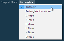
The first step when using the Schematic Geometry Wizard is to choose the building footprint shape – this is selected from the Footprint Shape drop-down menu.
The basic footprint shapes are as follows:
|
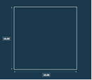
Rectangle
|
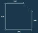
Rectangle (Minus Corner)
|
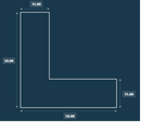
L Shape
|
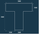
T Shape
|
|
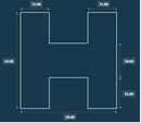
H Shape
|
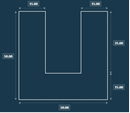
U Shape
|
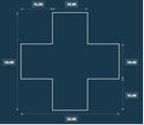
+ Shape
|
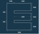
E Shape
|
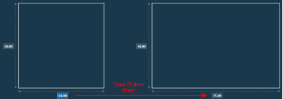
For each shape, where a dimension is adjustable a dotted arrow and a text box will be displayed. To edit the size of a dimension, click on the text box and type in the new size – you can then press Enter or simply click elsewhere on the footprint.
If you enter a value in the edit box that is invalid, the text will be displayed in red. Pressing Enter in this state will display a balloon tip indicating the issue (e.g. not a recognised floating-point value, or the value exceeds the permitted range). Note that the permitted range for the value will depend on the footprint itself and whether perimeter zones are to be used (see below). To reset the footprint dimensions back to their default values for the selected shape, right-click on the footprint and select Reset Dimension Sizes To Defaults.
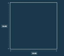
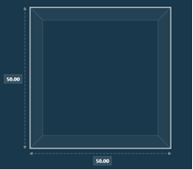
You can also choose whether or not perimeter zones should be created within the footprint. If perimeter zones are to be created, you can set the depth of the perimeter zones from the external walls and also whether or not internal partitions should be created for the perimeter zones (by default, they will not use partitions).
|
No Perimeter Zoning
|
With 4.5m Perimeter Zoning
|
To add perimeter zones to the building, tick the Add perimeter zones with depth checkbox – when ticked, this will enable the perimeter zone depth checkbox and also enable the Use partitions between perimeter and core checkbox (tick this to create internal partitions for the perimeter zones).
Note that perimeter zones are only created for the main floor area of each storey in the building – they will not be created for ceiling spaces, floor spaces or the roof (see Storeys & Roof).
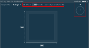
The final option that can be configured in this group is the Site Rotation for the building. In VE models, the site rotation is specified in degrees counter-clockwise. A text box is provided along the top of the group to indicate the value that is set, and a compass arrow is displayed to indicate the direction North will be with this value:
The site rotation can be set by manually entering a degree value into the Site Rotation text box, or by holding down the mouse pointer over the compass arrow and dragging it. Whilst dragging, you can cancel the change by pressing the Esc key – this will reset the site rotation back to the value it had before dragging the compass arrow.