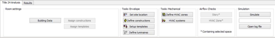
If no thermal zone is selected, the Building Data button can be seen at the bottom of the screen in the Room Settings section. This can be clicked to view the Building Data tab, Design Team tab and Address / City / State / Zip / Phone: contact details (input is optional).
Exceptional
Figure 13 – Building Data Button
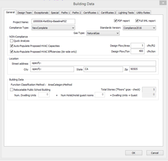
To access the following screen, click the Building Data button and select the General tab . This tab will be selected by default once the Building Data button is clicked.
Figure 14 – Project Data Tab
Input summary for the Project Data screen:
· Project Name: Name used for the project, if one is applicable
· PDF Report: Creates the PDF report of the simulation once simulation is complete
· Full XML Report: Creates a full XML report of the simulation once simulation is complete
· Compliance Type: Type of compliance analysis
o NewComplete – An all new, completely specified building. The building design includes the building envelope, lighting systems and HVAC systems. The proposed simulation model is based on user input, while the baseline simulation model will include envelope, lighting and HVAC systems that are generated by the software based on the ACM rules.
o NewEnvelope – An all new building with only the envelope design completed. This form of compliance might be used for a speculative office building where design of the lighting and HVAC systems is waiting for tenant input. In this type of compliance, the proposed and baseline simulation models will include lighting and HVAC systems that are generated by the software based on the ACM rules.
o NewEnvelopeAndLighting – An all new building with the envelope and lighting design completed. This form of compliance might be used for a speculative office building where design of the HVAC systems is waiting for tenant input. In this type of compliance, the proposed and baseline simulation models will include HVAC systems that are generated by the software based on the ACM rules.
o NewEnvelopeAndPartialLighting – An all new building with the envelope and part of the lighting design completed. This form of compliance might be used for a speculative office building where design of the lighting systems in tenant spaces and all of the HVAC systems are waiting for tenant input. In this type of compliance, the proposed and baseline simulation models will include HVAC systems that are generated by the software based on the ACM rules. The baseline simulation model will have all lighting generated by the rules, and the proposed model will include lighting systems generated by the rules for those areas where a lighting design has not been specified by the user.
o NewEnvelopeAndMechanical—an all new building with lighting design has been previously approved and approval is now being sought for the envelope and HVAC system. In this type of compliance, the proposed and baseline simulation models will both include lighting based on user input. The proposed model envelope and HVAC system will be based on user input but the baseline will be generated by the software based on the ACM rules.
o NewMechanical – An all new building where the envelope and lighting design has been previously approved and approval is now being sought for the HVAC system. In this type of compliance, the proposed and baseline simulation models will both include envelope and lighting based on user input. The proposed model HVAC system will be based on user input but the baseline will be generated by the software based on the ACM rules.
o NewMechanicalAndLighting – An all new building where the envelope has been previously approved and approval is now being sought for the lighting and HVAC systems. In this type of compliance, the proposed and baseline simulation models will both include the envelope based on user input. The proposed model lighting and HVAC systems will be based on user input but for the baseline these will be generated by the software based on the ACM rules.
o NewMechanicalAndPartialLighting – An all new building where the envelope and part of the lighting system has been previously approved and approval is now being sought for the remainder of the lighting and all of the HVAC systems. In this type of compliance, the proposed and baseline simulation models will both include envelope and the previously approved lighting based on user input. The proposed model will include the remaining lighting and all HVAC systems based on user input but for the baseline these will be generated by the software based on the ACM rules.
o ExistingAlteration—an existing building where envelope, lighting or HVAC systems are being altered or replaced, with no increase in building floor area. The proposed simulation is based on user input. The baseline simulation model will be based on user input for those portions marked as existing, while new or altered components will be replaced with software generated components based on the ACM rules. The simulation must include all altered portions of the building, as well as all existing, unaltered portions of the building which are served by HVAC systems that also serve altered portions. The simulation models may also include all or part of the remaining existing, unaltered portions of the building.
o ExistingAdditionAndAlteration—an all new addition to an existing building which is also being altered. This is a combination of ExistingAddition plus ExistingAlteration, and the rules for those compliance types apply.
o ExistingAddition option is now being replaced by additional partial compliance options which are similar to the New construction compliance options. These apply to additions only (new conditioned areas and systems) added to the existing building.
· AdditionComplete
· AdditionEnvelope
· AdditionEnvelopeAndLighting
· AdditionEnvelopeAndPartialLighting
· AdditionEnvelopeAndMechanical
· AdditionMechanical
· AdditionMechanicalAndLighting
· Gas Type: Selection of fuel used on site (other than electricity)
NON Compliance:
Quick Analysis uses the 13th, 26th, 39th, and 52nd weeks in a weather file because that set of weeks was found to minimize the differences between annual and Quick Analysis TDV energy results. The results from Quick Analysis may vary from the full annual simulation, so Quick Analysis cannot be used for your final compliance analysis and permitting.
· Auto-Populate Proposed HVAC Capacities (checkbox): For any HVAC component where the user has not specified a capacity value, the rules will calculate capacities based on the design flow/area and design flow/ton values below. Valid compliance analysis cannot be completed with this option checked, it is intended for use with other analysis objectives
· Auto Populate Proposed HVAC Efficiencies (Air-side only) (checkbox): For any HVAC component where the user has not specified an efficiency value, the rules will calculate an efficiency. Valid compliance analysis cannot be completed with this option checked, it is intended for use with other analysis objectives
· Design Flow/Area (cfm/ft2): A ratio used to determine airflow capacity of HVAC components when “Auto-Populate Proposed HVAC Capacities” is checked
· Design Flow/Ton (cfm/ton): A ratio used to determine cooling capacity of HVAC components when “Auto-Populate Proposed HVAC Capacities” is checked.
Please Note: Title 24 Compliance requires that user model HVAC equipment have all capacity and efficiency inputs entered. For analysis that is not intended for compliance, these inputs may not be known. These inputs allow the user to activate rules of thumb to provide required equipment capacities, and to tailor these inputs if desired. However, if the box is checked, the run results cannot be used to show compliance with the energy code
Location s ection:
· Street Address : Street address where the project is located
· City : City where the project is located
· State : State where the project is located
· Zip Code : ZIP code where the project is located. Location and Weather File date defaulted based on this value.
Building Data section:
· Function Class ification Method : The method of specifying functional area types. Identifies whether functional area types will be assigned using the Complete Building Method or the Area Category Method
· Relocatable Public School Building (checkbox): If yes, check the box
· Total Stories (“Floors” grps – check): The total number of stories in a building. Includes both above grade stories and any below grade stories (Please see Section 0 )
· Num Dwelling units: The number of high rise Residential units within the building
· Num Hotel/motel guest rooms: The number of Hotel/motel guest rooms within the building
· Dwelling Units + Guest: The total number of residential or hotel/motel living units in the building.
Building Stories
The total number of stories, as displayed on the Building Data > Project Data tab (Section 4.4.1), is calculated based on the number of “Room Groups” in the “Floors” grouping scheme. The user should create a separate room group for each floor of their model and assign all thermal zones of a floor to the appropriate room group. Please refer to the ModelIT User Guide available in the IESVE Support User Guide section of the IESVE website for details on how to use “Room Groups”.
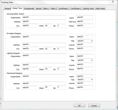
Design Team
To access this screen, click the Building Data button and select the Design Team tab .
Figure 15 – Design Team Tab
Input summary for the Design Team tab:
Documentation Author Info section
· Organization: Documentation Author Organization (input is optional).
· Name: Documentation Author primary contact name (input is optional).
· CEA Num : Documentation Author Certified Assessor Number (input is optional).
· Address / City / State / Zip / Phone: contact details (input is optional).
Envelope Designer Info section
· Organization: Architect Organization (input is optional).
· Name: Architect primary contact name (input is optional).
· Title: Architect primary contact title (input is optional).
· License : Architect license number (input is optional).
· Address / City / State / Zip / Phone: contact details (input is optional).
Lighting Designer Info section
· Organization: Lighting Designer Organization (input is optional).
· Name: Lighting Designer primary contact name (input is optional).
· Title: Lighting Designer primary contact title (input is optional).
· License : Lighting Designer license number (input is optional).
· Address / City / State / Zip / Phone: contact details (input is optional).
Mechanical Designer Info section
· Organization: HVAC Engineer Organization (input is optional).
· Name: HVAC Engineer primary contact name (input is optional).
· Title: HVAC Engineer primary contact title (input is optional).
· License : HVAC Engineer license number (input is optional).
· Address / City / State / Zip / Phone: contact details (input is optional).
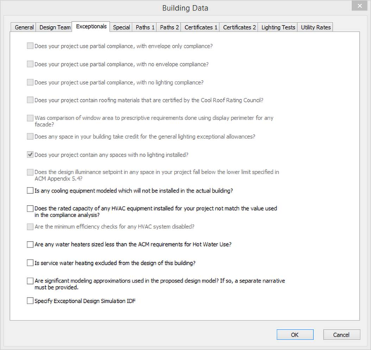
Exceptionals
To access this screen, click the Building Data button and select the Address / City / State / Zip / Phone: contact details (input is optional).
Exceptional tab .
Figure 16 – Exceptional Conditions tab
Input summary for the Exceptional Conditions tab:
If any of the exceptional conditions apply to your project, mark that item using the tick box provided. The compliance forms will include guidance for the code reviewer to check the exceptional conditions for compliance.
· Specify Exceptional Design Simulation IDF : When a building cannot be adequately modeled within CBECC, select a modified EnergyPlus IDF with all the capabilities available to EnergyPlus for CBECC to compare with the baseline. Note: Simulating with this option results in a non-compliant run and the resulting performance compliance report will be watermarked as not usable for compliance.
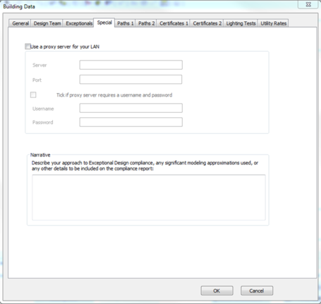
Special
Proxy Server
Figure 17 – Proxy settings tab
In order for the reports to be generated the machine must be connected to the internet and as such a proxy may be required.
Input summary for the Proxy Settings tab:
Use a proxy server for your LAN (tickbox):
· Server
· Port
Tick if proxy server requires a username and password (tickbox):
· Username
· Password
It is recommended to consult your IT network administrator for assistance in configuring a proxy in order to allow connection to the server at t24docs.com
Further, if your proxy server encodes and decodes https traffic then it is necessary to add your Root Certificate Data at the bottom of the following file (the “bundle fo CA Root certificates”) in the local CBECC-COM installation directory (typically this is at C:\Program Files (x86)\CBECC-Com 2013\curl-ca-bundle.crt).
Narrative
Input summary for the Narrative section:
Additional Remarks: A description of any exceptional modeling details or designs to be reviewed by the building department. This is required if the following Exceptional condition has been checked:
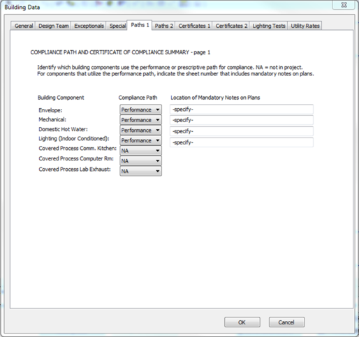
Paths 1
To access this screen, in the Building Data navigate to Paths 1 tab.
Figure 18 – Paths 1 tab
Input summary for the Paths 1 tab:
· Compliance Path : The choice of Performance, Prescriptive, or NA is available for each building component to move through compliance.
· Location of Mandatory Notes on Plans : Enter the location where the notes of the building component compliance path can be found.
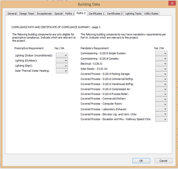
Paths 2
To access this screen, in the Building Data navigate to Paths 2 tab.
Figure 19 –Paths 2 tab
Input summary for the Paths 2 tab:
· Prescriptive Requirement : Select Yes or NA for each prescriptive requirement.
· Mandatory Requirement : Select Yes or NA for each mandatory requirement.
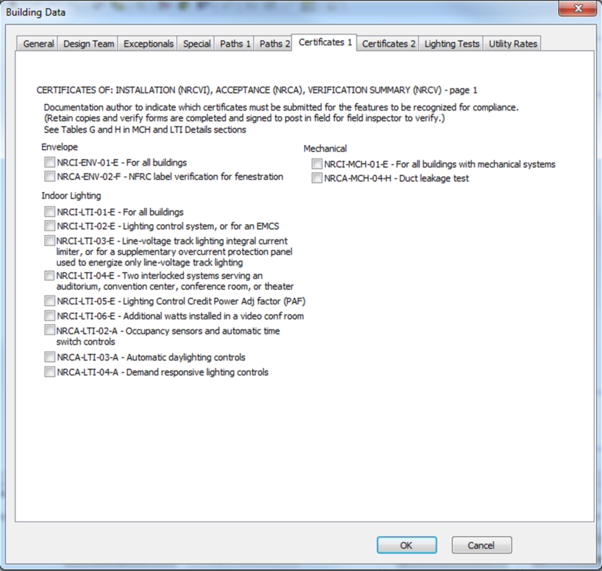
Certificates 1
To access this screen, in the Building Data navigate to Certificates 1 tab.
Figure 20 – Certificates 1 Tab
Input summary for the Certificates 1 tab:
Certificates of Installation : Select the forms (certificate installation, certificate of acceptance and certificate of verification summary forms) that must be submitted for the features to be recognized for compliance.
Certificates 2
To access this screen, in the Building Data navigate to Certificates 2 tab.
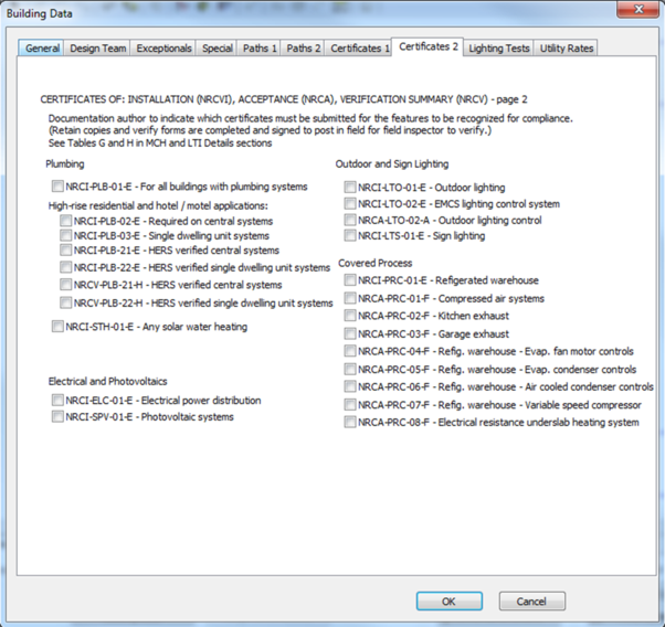
Figure 21 – Certificates 2 Tab
Input summary for the Certificates 2 tab:
· Certificates of Installation : Select the forms (certificate installation, certificate of acceptance and certificate of verification summary forms that must be submitted for the features to be recognized for compliance.
Lighting Tests
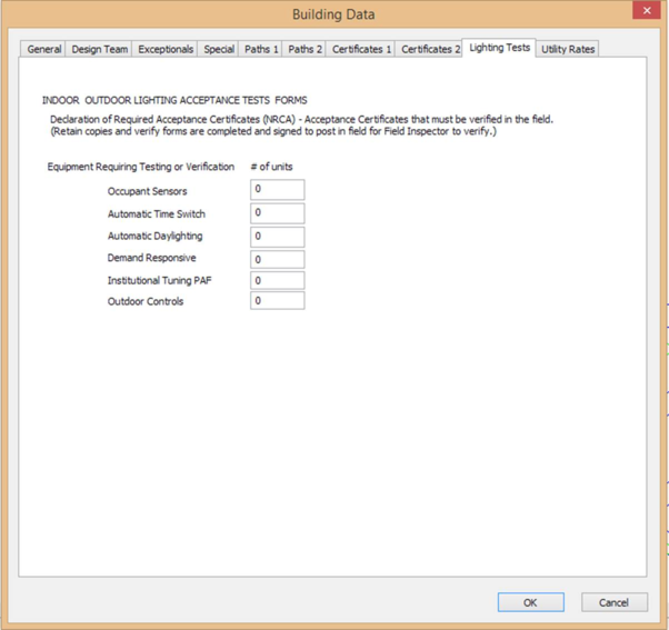
To access this screen, in the Building Data navigate to Lighting Tests tab.
Figure 22 – Lighting Tests Tab
Input summary for the Lighting Tests tab:
· Equipment Requiring Testing or Verification : Specify the number of units for each type of control requiring testing or verification.
For Acceptance Certificates regarding lighting equipment see Certificate 1, 2 tabs
Utility Rates
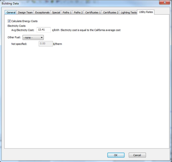
To access this screen, in the Building Data navigate to Utility Tests tab.
Figure 23 – Utility Rates Tab
Input summary for the Utility Rates tab:
· Calculate Energy Costs : Select to indicate whether the energy cost calculations are to be performed (does not impact Title 24 Pass/Fail or compliance margins).
Electricity Costs section
· Avg Electricity Cost : The average electricity cost. (Input is optional.)
· Other Fuel : Select other fuel used on site if applicable. Options are none, NaturalGas, Propane, and FuelOil#2.
On completion of a successful simulation with Calculate Energy Costs turned on, the output costs will be located at the bottom of the ResultsAnalysis.xml.
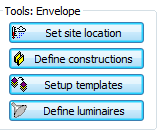
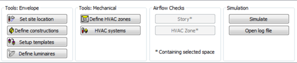
Set site location
To set site location, the user should click the “Set site location” button (Figure 24)
Figure 24 – Set Site Location Button
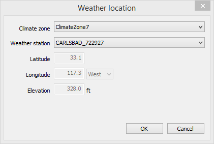
Figure 25 – Weather Location Dialog
Location and Weather File date defaulted based on the ZIP code input by the user on the Building Data > Project Data tab.
· Climate Zone : California Climate zone
· Weather Station : California weather station
Constructions
Please refer to the Constructions Database User Guide available in the IESVE Support User Guide section of the IESVE website.
Further directions specific to Title 24 modelling are listed in this section.
Defining a Construction
Opaque and glazed constructions can be defined using the “Define constructions” button (Figure 26) which opens the Constructions Database tool.

Figure 26 – Define constructions button
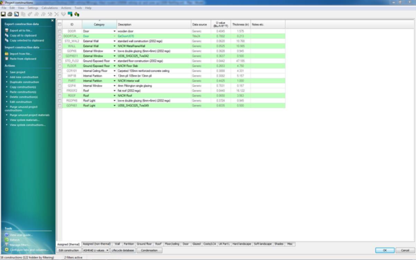
Figure 27 – Constructions Database default view
Materials
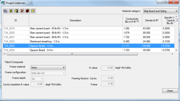
All materials that can be used for a Title 24 compliance simulation have been created for the user. These can be found in Constructions Database > View Menu > Project Materials (Figure 28). Please refer to the Constructions Database User Guide available in the IESVE Support User Guide section of the IESVE website.
Figure 28 – Project Materials Title 24
Only the specific set of air cavity thicknesses for each construction category outlined in Table 3 can be used for Title 24 Compliance simulation.
Table 3 – Air Cavity Thickness
|
Construction Type
|
Ceiling
|
Floor
|
Roof
|
Wall
|
|
(Thickness)
|
|
1/2 in.
|
X
|
X
|
X
|
X
|
|
3/4 in.
|
X
|
X
|
X
|
X
|
|
1 1/2 in.
|
X
|
X
|
X
|
X
|
|
3 1/2 in.
|
X
|
X
|
X
|
X
|
|
4 in. or more
|
X
|
|
X
|
X
|
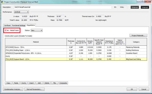
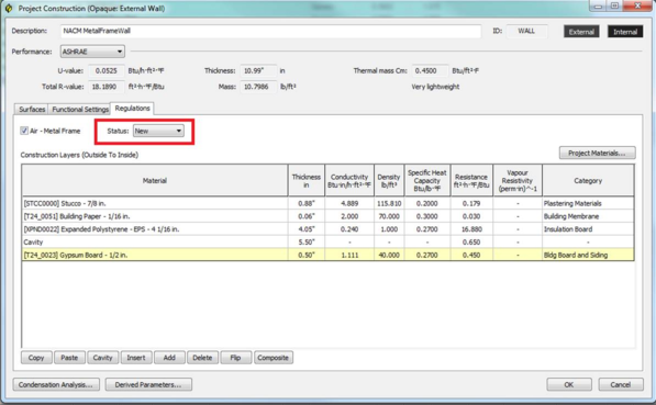
Each air cavity in VE constructions will be rounded to the nearest thickness of this set at the point of simulation, with the exception of a special case “Air - Metal Wall Framing - 16 or 24 in. OC”, which is defined by the Wall construction > Air – Metal Frame checkbox (Figure 29).
Figure 29 – Metal Framed Air Cavity tick box
Composite materials
To assign a composite material to a construction, the user must first select a material that is outside of the composite material. The composite material will be assigned to this material. The user will then click the “Project materials” button.
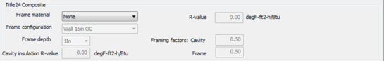
Then using the Title 24 Composite material dropdowns (Figure 30), the composite material can be assigned to the highlighted material.
Figure 30 – Title 24 Composite Materials
Input summary for Title 24 Composites (Figure 30):
· Frame Material : The framing is constructed with the selected material
· Frame Configuration : The framing is constructed with the selected configuration
· Frame Depth : The framing is constructed with the selected depth.
· Cavity Insulation R-Va lue : Nominal R-value of composite layer cavity insulation.
Construction Status
To enter the status of a construction, the user should use status dropdown located in the Regulations section of the specific constructions dialog
Figure 31 – Construction Status
Input summary for Title 24 Construction Status (Figure 31):
· Status : Construction Status. Options are New, Altered and Existing
Visible Absorptance/Visible Reflectance
A constructions visible absorptance can be entered as using the visible light reflectance fields (Figure 32).
Equation 1 – Visible Light Absorptance
The visible light reflectance input fields can be accessed via Surfaces section in the specific construction.
Figure 32 – Visible Light Reflectance
Underground Walls
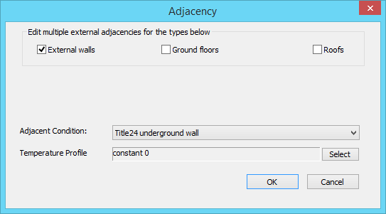
An underground wall is defined via the Adjacency toolbar button

and applying the adjacent condition of “Title24 underground wall”. Please refer to the Apache View User Guide available in the IESVE Support User Guide section of the IESVE website for further guidance.
Figure 33 – Underground wall Adjacency
Underground Floor
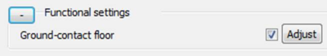
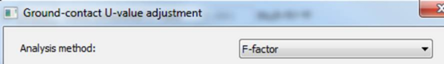
An underground floor can be defined utilizing the F-factor analysis method. This can be done in the Functional Settings screen by:
· Ticking the “Ground-contact floor” tick box (Figure 34)
· Then click “Adjust” (Figure 34)
· Change Analysis method to F-Factor (Figure 35)
· Press OK
Figure 34 – Ground-contact floor
Figure 35 – F-Factor Analysis Method
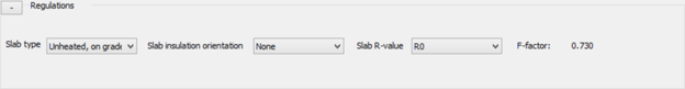
The F-factor used in the simulation will be determined by the three slab parameters (Figure 36)
Figure 36 – Underground floor parameters
Input summary for Underground Floor Slab:
· Slab Type : The Underground slab type (Heated or Unheated, On Grade or Below Grade)
· Slab insulation orientation : The location and extent of slab-on-grade floor insulation
· Slab R-Value : Nominal R-value of the underground floor slab
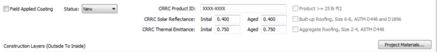
Roof
Figure 37 – Roof Regulations
Input summary for Roof Surface Properties:
· Field Applied Coating (checkbox): This indicates if a roofing surface is from a coating applied on site or not.
· CRRC: Solar Reflectance (Initial): The Initial Reflectance value from Cool Roof Rating Council (CRRC) testing of the roofing
· CRRC: Solar Reflectance (Aged): The Aged Reflectance value from Cool Roof Rating Council testing of the roofing
· CRRC: Thermal Emittance (Initial): The Initial Emittance value from Cool Roof Rating Council testing of the roofing
· CRRC: Thermal Emittance (Aged): The Aged Emittance value from Cool Roof Rating Council testing of the roofing
· CRRC Product ID: A string of letters or numbers serving as a unique identifier of the coating
· Product >= 25 lb ft2: Check box for Products >= 25 lb/ft2.
· Built-Up Roofing, Size 6-8, ASTM D448 and D1896: check this box for built up roofing with
size 6-8 complying with ASTM D448 and D1896
· Aggregate Roofing, Size 2-4, ASTM D448: check this box for aggregate roofing with size 2-4
complying with ASTM D448
Door
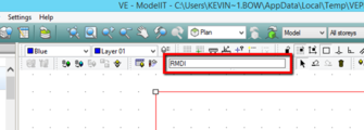
Internal doors should be omitted from Title24 models. If they have been included, they should be deleted in ModelIT. This can be done quickly by selecting all spaces in your model and in ModelIT type “RMDI” in the key-in field. It would be advised to save a copy of your model prior to performing this operation as it cannot be undone after leaving ModelIT.
Figure 38 – ModelIT Key-in Field
Figure 39 – Door Regulations
Input summary for Door properties:
A doors construction can be set as “Swinging” or “Non-swinging”. The default setting is “Swinging” but can be changed using the “Non-swinging” tick box
Certification Method: Options are DefaultPerformance or NRFCRated
Type: The type of door. Options are:
· MetalInsulatedSingleLayerSectionalDoor
· MetalInsulatedSwingingDoor
· MetalUninsulatedDoubleLayerDoor
· MetalUninsulatedSingleLayerDoor
· MetalUninsulatedSingleLayerRollupDoor
· WoodLessThan1.75inThickDoor
· WoodGreaterThanorEqualTo1.75inThickDoor
For a ‘DefaultPerformance’ certified door, the Type sets a fixed U value.
Glazed Construction
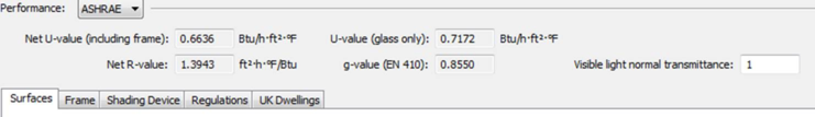
The exact materials used to define Layers are not passed to the Title24 simulation. Only the number of panes is relevant. You therefore have some freedom in how to meet the required SHGC / U values, which must be derived under the ASHRAE ‘Performance’ method, and appear on UI thus:
SHGC 'g-value (EN-410)'
SHGC (Centre of glass) appears at bottom of

dialog
U-value 'Net U-value (including frame)'
U-value (Centre of Glass) 'U-value (glass only)'
Figure 40: Glazing constructions tab
Note: when the Certification method (Regulations tab) is set to ‘Default Performance’ only the Centre-of-glass parameters are used in the simulation.
In addition, only the following inputs are relevant:
· Visible light normal transmittance (as shown above)
· Frame tab > Frame type
· Shading Device tab > Local & External shade (both or neither) – see next section
· Regulations tab > all items (similar to CBECC-Com’s Fenestration).
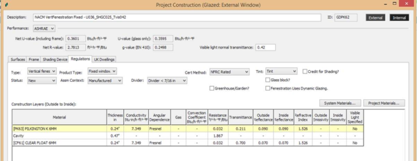
Figure 41 - Regulations tab in glazed constructions
Input summary for Fenestration Construction Data:
· Type : Select the fenestration type. Options are VerticalFenestration and Skylight.
· Assm. Context : Select whether the fenestration product is Manufactured, Site Built or Field Fabricated.
· Cert. Method : Select whether the fenestration construction represents an actual National Fenestration Rating Council (NFRC)-rated product (i.e., uses Center of Glass values via the Nonresidential Appendix 6 [NA-6] equation method), or is based on T-24 Default Assumptions.
· Product Type : Select whether the fenestration product is for a FixedWindow, operable Window, Curtain Wall or Glazed Door.
· Fenestration Uses Dynamic Glazing (checkbox) : Indicates whether the fenestration construction is used for dynamic glazing. This is used for reporting purposes only.
· Credit for Shading? (check box) : Select to indicate if any fenestration in the building is taking compliance credit for shading (modeled as overhangs/fins). This input is for reporting purposes only and does not result in a credit by checking the box.
Exterior Shading Object
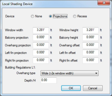
All geometric shading bodies created in ModelIT that are assigned the property of “Adjacent Building”, “Topographical Shade” or “Local shade” are omitted from Title24 simulation. The shading bodies do not need to be deleted in ModelIT, however they should be accounted for with shading tool in the Title24 module for compliance analysis in Project Constructions > Glazed, as below;
An external shading object can be entered in a Glazed construction.
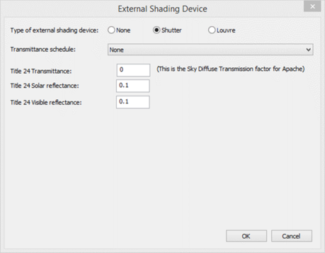
Note: both of Local shade, which defines the projections, and External shade, which defines transmittance (either constant or profiled), must be defined to complete the definition of a Title 24 shade.
Figure 42 – Shading Devices
Figure 43 – Local Shading > Projections
Figure 44 – External Shading > Shutter
If a transmittance schedule other than ‘None’ is defined, the constant Transmittance does not apply and will be hidden.
Assigning a Construction
A construction can be assigned using the Assign Constructions icon

. Please refer to the Apache View User Guide available in the IESVE Support User Guide section of the IESVE website.
Schedules/Profiles
All schedules that can be assigned in Title 24 Compliance have been created for the user. These schedules can be interrogated in ApPro. Please refer to the ApPro User Guide available in the IESVE Support User Guide section of the IESVE website.
Setup templates
Templates for space data can be created using the “Setup templates” button (Figure 45).
Figure 45 – Setup Templates button
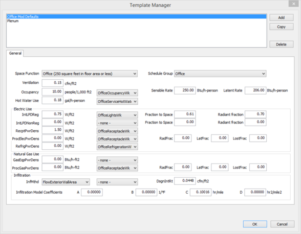
Figure 46 – Template Manager
Input summary for the Template Manager screen:
· Space Function : The area category occupancy type from Nonresidential Appendix 5.4A
· Schedule Group : A type specifying occupancy categories used to determine schedules
· Ventilation : The amount of outside air provided to a space during occupied hours divided by the floor area of that space
· Occupancy : The area density of people associated with a space expressed in people per 1000 square feet
· Schedules (Occupancy) : Reference to a schedule that describes the fraction of occupancy on an hourly basis
· Sensible Rate : The rate of sensible heat released per person, which is a function of activity
· Latent Rate : The rate of latent heat released per person, which is a function of activity
· Hot Water Use : The amount of hot water for each person in a space during occupied hours
· Schedules (HotWater use ): Reference to a schedule that describes the fraction of hot water use on an hourly basis
Electric Use section :
· IntLPDReg: Total regulated connected lighting power density for all interior lighting systems in a Space. This includes the loads for lamps and ballasts
o Schedules (drop-down box) : Reference to a schedule that describes interior lighting use
o Fraction to Space : Fraction of regulated interior lighting heat gain going to space air
o Radiant Fraction : Fraction of regulated interior lighting radiant heat gain going to space surfaces
· IntPDNonReg : Total non-regulated connected lighting power density for all interior lighting systems in a Space. This includes the loads for lamps and ballasts
o Schedules drop-down box : Reference to a schedule that describes the fraction of lighting use on an hourly basis
o Fraction to Space : Fraction of non-regulated interior lighting heat gain going to space air
o Radiant Fraction : Fraction of non-regulated interior lighting radiant heat gain going to space surfaces
· RecptPwrDens : The usage of electrical devices plugged into receptacles in a space based on the occupancy type
o Schedules (drop-down box): Reference to a schedule that describes the fraction of receptacle use on an hourly basis
· ProcElecPwrDens : Process electrical power density resulting from an activity or treatment not related to the space conditioning, lighting, service water heating, or ventilating of a building as it relates to human occupancy. Process load may include sensible and/or latent components. For data centers this includes transformers, UPS, PDU, server fans, power supplies, etc
o Schedules (drop-down box) : Reference to a schedule that describes fraction of process electric use on an hourly basis
o RadFrac : The fraction of radiant heat gain to a space based on appliance energy use
o LatFrac : The fraction of latent heat gain to a space based on appliance energy use
o LostFrac : The fraction of heat lost to the exterior is based on appliance energy use
· RefrigPwrDens : The energy consumption of commercial refrigeration equipment in a space expressed in watts per square foot of space floor area. Commercial refrigeration EPD is used for walk in freezers, walk in coolers, and refrigerated casework. Other equipment such as Plug in coolers, vending machines and plug in refrigerators should be accounted for in receptacle loads
o Schedules (drop -down box) : Reference to a schedule that describes fraction of refrigeration use on an hourly basis
Natural Gas Use section :
· GasEqpPwrDens: Commercial gas power density is the average power density for all commercial gas equipment, assuming constant year-round operation
o Schedules (drop-down box): Reference to a schedule that describes the fraction of gas equipment use on an hourly basis
· ProcGasPwrDens: Process load is the gas energy consumption in the conditioned space of a building resulting from an activity or treatment not related to the space conditioning, lighting, service water heating, or ventilating of a building as it relates to human occupancy. Process load may include convective (sensible) and/or latent components
o Schedules (drop-down box): Reference to a schedule that describes the fraction of receptacle use on an hourly basis.
o RadFrac: The fraction of radiant heat gain to a space based on appliance energy use
o LatFrac: The fraction of latent heat gain to a space based on appliance energy use
o LostFrac: The fraction of heat lost to the exterior based on appliance energy use
Infiltration section:
· InfMthd: Method used for modeling uncontrolled air leakage or infiltration. Options include FlowZone, FlowArea, FlowExteriorArea, FlowExteriorWallArea, and AirChangesPerHour.
· DsgnInfRt: The infiltration rate specified as cfm/ft² of exterior wall area at a wind speed of 10 mph and an infiltration schedule value of 1. The default value of 0.0448 cfm/ft² must be used unless specific air sealing methods beyond requirements of the standard are applied and documented.
· Infiltration Model Coefficients A: Infiltration overall coefficient.
· Infiltration Model Coefficients B: Infiltration temperature coefficient.
· Infiltration Model Coefficients C: Infiltration windspeed coefficient.
· Infiltration Model Coefficients D: Infiltration windspeed squared coefficient.
Assign template to selection set
A template can be assigned to an individual or selection of spaces using the Assign Room Thermal Template icon

. Please refer to the Apache View User Guide available in the IESVE Support User Guide section of the IESVE website.
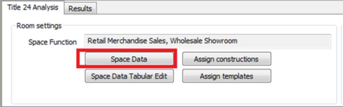
Space Data
To access this screen, click a thermal zone in the model viewer window and then the “Space Data” button.
Figure 47 – Space Data button
General
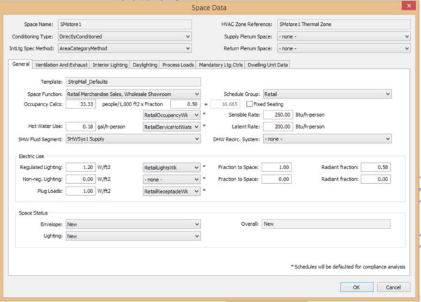
Figure 48 – Space Data General Tab
Input summary for Space Data dialog:
· Space Name : The name of the active space
· Conditioning Type : One of a list of categories that characterize the type of conditioning for the space
· IntLtg Spec Method : The method for selecting baseline lighting and other loads for a space
· HVAC Zone Reference : This is a reference to the HVAC zone that serves a given space (Section 4.10 )
· Supply Plenum Space : The name of the supply air plenum space for the current Space
· Return Plenum Space : The name of the return air plenum space for the current Space
The Space Data > General tab shows the following input information:
· Template: The template that has been assigned to the space
· Space Function : The area category occupancy type from Nonresidential Appendix 5.4A.
· Schedule Group : A type specifying occupancy categories used to determine schedules.
· Fixed Seating (check box) : A flag to indicate that the space has fixed seating and the space occupancy will be entered as number of occupants.
· Occupancy Calcs : The areal density of people associated with a space expressed in people per 1000 square feet.
· Fraction : The expected fraction of the exiting density of people in a Space, based on SpaceFunction, which will determine the design occupancy.
· Sensible Rate : The sensible heat of an occupant expressed in Btu per hour person.
· Latent Rate : The latent heat of an occupant expressed in Btu per hour person.
· Schedule Name* (Occupancy) : Reference to a unique occupant Schedule Name. (Schedules will be defaulted for compliance analysis.)
· Hot Water Use (gal/h-person) : The amount of energy required to provide hot water for each person in a space during occupied hours.
· Schedule Name* (Hot Water Use) : Reference to a unique hot water heating Schedule
· SHW Fluid Seg ment : Select the service hot water loop coming into the space.
· DHW Recirc . Sy stem : Select the domestic hot water loop coming into the space.
Electric Use section
· Regulated Lighting: Total regulated connected lighting power density for all interior lighting systems in a Space. This includes the loads for lamps and ballasts.
· Fraction to Space (Regulated Lighting): Fraction of regulated interior lighting heat gain going to space air.
· Radiant Fraction (Regulated Lighting): Fraction of regulated interior lighting radiant heat gain going to space surfaces.
· NonReg. Lighting: Total non-regulated connected lighting power density for all interior lighting systems in a Space. This includes the loads for lamps and ballasts.
· Fraction to Space (NonReg. Lighting): Fraction of non-regulated interior lighting heat gain going to space air.
· Radiant Fraction (NonReg. Lighting): Fraction of non-regulated interior lighting radiant heat gain going to space surfaces.
· Plug Loads: The usage of electrical devices plugged into receptacles in a space based on the occupancy type.
· Schedules (Regulated Lighting): Reference to a schedule that describes a regulated interior lighting system.
· Schedules (NonReg. Lighting): Reference to a schedule that describes a nonregulated interior lighting system.
· Schedules (Plug Loads): Reference to a schedule that describes plug load use.
Space Status section:
· Envelope : Options are New, Altered and Existing
· Lighting : Options are New, Altered, Existing and Future
· Overall : This is a calculated status based on your Envelope and Lighting status for the space
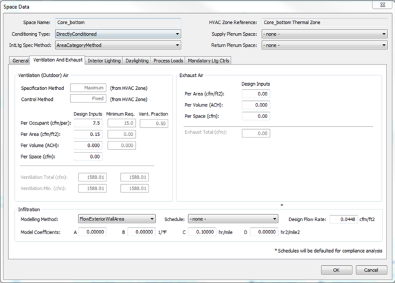
Ventilation and Exhaust
Figure 49 – Ventilation and Exhaust
Ventilation (Outdoor) Air section:
· Specification Method: The method used to calculate the design ventilation flow for the ThermalZone
· Control Method: The method used to vary the ventilation flow.
· Per Occupant (cfm/per): The user input outdoor air flow rate divided by the design or hourly occupancy of the space
· Per Area (cfm/ft2): The user input outdoor air flow rate divided by the floor area of the space
· Per Volume (ACH): The user input outdoor air flow rate in cubic feet per hour divided by the volume of the space
· Per Space (cfm): The user input outdoor air flow rate in cubic feet per minute for the space.
· Ventilation Total (cfm): The quantity of ventilation air provided to the Space, based on the specification method defined at the Thermal Zone.
· Ventilation Min. (cfm): The outside air flow rate of the Space for simulation
· Minimum Req.: The code minimum quantity of ventilation air provided to the space
o Per Volume (ACH): The code minimum amount of outside air provided to a space during occupied hours, divided by the volume of the space.
o Per Area (cfm/ft2): The code minimum amount of outside air provided to a space during occupied hours, divided by the floor area of that space.
o Per Occupant (cfm): The code minimum amount of outside air provided to a space during occupied hours, divided by the design number of people in the space.
· Vent Fraction: The fraction of design occupancy that is assumed for calculating the minimum design ventilation rate for compliance analysis
Exhaust Air section:
· Per Area (cfm/ft2): The design exhaust air flow rate in CFM/ft2 for the Space
· Per Volume (ACH): The design exhaust air flow rate in ACH for the Space
· Per Space (cfm): The design exhaust air flow rate in CFM for the Space
· Exhaust Total (cfm): The design exhaust air flow rate in CFM for the Space
Infiltration section:
· Modeling Method: The method to model infiltration.
· Schedule Name*: The user input schedule for infiltration modelling. (Schedules will be defaulted for compliance analysis.)
· Design Flow Rate: The quantity of air infiltrating the space in cfm/ft2
· Model Coefficients A (none): The constant infiltration coefficient
· Model Coefficients B (1/°F): The infiltration coefficient with units 1/°F
· Model Coefficients C (hr/mile): The infiltration coefficient with units hr/mile
· Model Coefficients D (hr2/mile2): The infiltration coefficient with units hr2/mile2
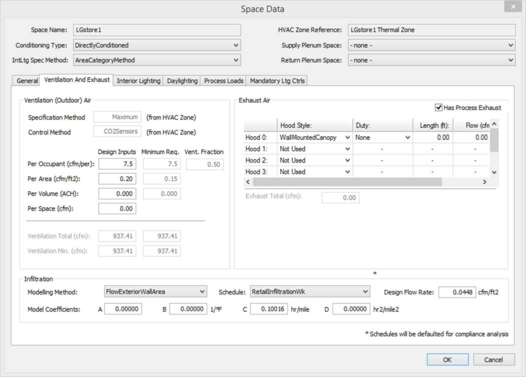
Space Data Screen (Ventilation and Exhaust Tab—Kitchen, Commercial):
Figure 50 – Ventilation and Exhaust (Kitchen Hood)
This is available only for spaces of function type Kitchen in the Function field of the Space Data tab.
Exhaust Air section:
· Exhaust Hood Style: Select the type of exhaust hood. Input is optional. Options are WallMountedCanopy, SingleIsland, DoubleIsland, Eyebrow, BackshelfOrPassover
· Duty: Select the type of duty. Input is optional. Options are none, light, Medium, or Heavy
· Length (ft): Enter length of hood in feet
· Flow (cfm): The air flow rate in cfm
· Exhaust Total (cfm): The design exhaust air flow rate in cfm for the Space
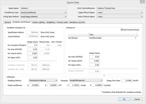
For Spaces of type Laboratory with Process Exhaust choose Lab exhaust type. Options available are:
· Load Dominated
· Hood Dominated
Figure 51 – Lab exhaust
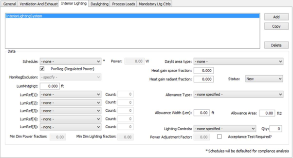
Interior lighting
To use this tab, users must have previously defined their luminaires in the “Define luminaires” dialog (Section 4.9).
Figure 52 – Interior Lighting
Input summary for Interior Lighting data:
· Schedule: Reference to a unique Schedule Name of interior type for association with an interior lighting system
· Power : Luminaire power (taking Count into account)
· PwrReg (Regulated Power): Whether this lighting system's power is Regulated vs. Non- Regulated. Defaults to True (regulated)
· Daylit Area Type : The origin of the daylight
· LumMntgHgt: The Luminaire Height of an IntLtgSys, only necessary for Tailored Method Baseline General and Additional Lighting Power Allowances. Assumed by default to be the same as the space floor to ceiling height
· LumRef[1] , Count : Whether or not first luminaire is assigned. Its count (if assigned, must be > 0)
· LumRef[2] , Count : Whether or not second luminaire is assigned. Its count (if assigned, must be > 0) .. .. etc
· Heat Gain Space Fraction: Fraction of interior lighting heat gain going to space air
· Heat Gain Radiant Fraction : Fraction of interior lighting radiant heat gain going to space surfaces
· Status : Options are New, Altered, Existing and Future
· Min Dim Power Fraction: The power fraction at minimum dimming
· Min Dim Lighting Fraction: The lighting fraction at minimum dimming
· Allowance Type : Custom Lighting Power Allow ance Type for Interior Lighting. Available options depend on Space function , and whether Tailored Method or Category Method
· Allowance Width (Len): The Width (ft) of Chalk/Display Board to which the Area Category or Tailored Allowance (W/ft) is applied
· Allowance Area : The Area (ft2) of to which the Area Category or Tailored Allowance (W/ft2) is applied
Lighting Controls: allows the software to apply the power adjustment factors (PAF), see below.
· PartialOnOccupantSensingControl
· OccupantSensingControls-1to125SF
· OccupantSensingControls-126to250SF
· OccupantSensingControls-251to500SF
· ManualDimming
· MultisceneProgrammableControls
· DemandResponsiveControl
· CombinedManualDimmingPlusPartialOnOccupantSensingControl
Power Adjustment Factor: Power adjustment factors (PAFs) represent the percent reduction in lighting power that will approximate the effect of the control. Models account for such controls by multiplying the controlled watts by (1-PAF).
Daylight control
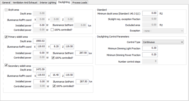
Figure 53 – Daylight control
Input summary for the Daylighting tab:
· Daylighting Control Positions: Each daylit area type (Skylit, Primary Sidelit, and Secondary Sidelit) is automatically assigned a daylighting control position, which controls how the space lighting responds to the daylight illuminance measured at the control position. Each daylighting control position utilizes the following inputs:
· Skylit area: The skylit area is the portion of the floor area that gets daylighting from a skylight.
· Primary sidelit area: The primary sidelit daylit area is the portion of the floor area that gets the highest illumination from a window. Primary sidelit daylit area is defined as a band near the window with a depth equal to the distance from the floor to the top of the window and width equal to window width plus 0.5 times window head height wide on each side of the window opening.
· Secondary sidelit area: The secondary sidelit daylit area is the portion of the floor area that gets less high, but still useful daylighting from a window. Secondary sidelit daylit area is defined as a band beyond the primary daylighted area that extends a distance double the distance from the floor to the top of the window and width equal to window width plus 0.5 times window head height wide on each side of the window opening.
· Illuminance RefPt coord: The position of the daylight reference points within the daylit space, identified by the Cartesian X, Y, and Z position of the reference point (feet), with respect to the overall project coordinate system.
· Illuminance SetPoint: The design illuminance for the daylit area associated with the Daylighting Control Position. Lighting controls are simulated so that the illuminance at the reference position is always maintained at or above the illuminance setpoint.
· Installed Power : The total lighting power of all luminaires located within the Zone.
· Controlled Power: The total lighting power (Watts) controlled by daylighting controls associated with the Daylighting Control Position.
· 100% Controlled (check box): If checked, this indicates that 100% of the installed lighting power in Skylit, Primary Sidelit or Secondary Sidelit Daylit Zone is controlled by the associated daylighting control position.
Standard Section:
· Minimum Daylit Area per 2013 T-24 Standards Sec.140.3(c): Area Required to be daylit (Skylit plus Primary Sidelit) by Section 140.3c of Title 24 Standards.
· Skylt. Req. Exception Fraction: The fraction of floor area that is exempt from the Minimum Daylit Area requirement (2013 T-24 Standards Sec.140.3(c)).
· Excluded Area: Total area excepted from the skylight Minimum Daylit Area requirement.
· Exception: The specific exception to the Minimum Daylit Area requirement. Possible exceptions include:
o The building is not located in climate zone 1 or climate zone 16 (automatically identified by CBECC software).
o Designed general lighting is less than 0.5 W/ft2 (automatically identified by CBECC software).
o Existing walls on plans result in enclosed spaces less than 5,000 ft2
o Future walls or ceilings on plans result in enclosed spaces less than 5,000 ft2 or ceiling heights less than 15 feet.
o Plans or documents show that space is an auditorium, religious building of worship, movie theater, museum, or refrigerated warehouse.
Daylighting Control Parameters: The following inputs describe the daylighting control algorithm for all of the controls located within a particular space.
· Control Type: The type of control that is used to control the electric lighting in response to daylight available at the reference point. The options are:
o Continuous Dimming controls have a fraction to rated power to fraction of rated output that is a linear interpolation of the minimum power fraction at the minimum diming light fraction to rated power (power fraction = 1.0) at full light output
o Continuous Dimming + Off controls are the same as continuous dimming controls except that these controls can turn all the way off when none of the controlled light output is needed.
o Stepped Switching Controls vary the electric input power and lighting output power in discrete equally spaced steps. See At each step, the fraction of light output is equal to the fraction of rated power.
· Minimum Dimming Light Fraction: Minimum light output of controlled lighting when fully dimmed. Minimum light fraction = (Minimum light output) / (Rated light output)
· Minimum Dimming Power Fraction: The minimum power fraction when controlled lighting is fully dimmed. Minimum power fraction = (Minimum power) / (Full rated power)
· Number Control Steps: Number of control steps. For step dimming, identifies number of steps that require fraction of rated light output and rated power fraction
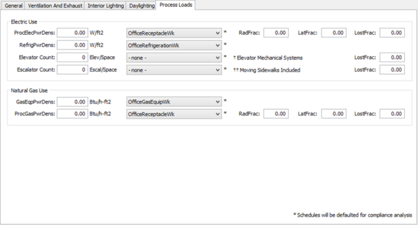
Process Loads
Figure 54 – Process and Airflow
Input summary for the Space Data screen ( Process and Airflow tab):
Electric Use section
· Process Electric: Process load is the electric energy consumption in the conditioned space of a building resulting from an activity or treatment not related to the space conditioning, lighting, service water heating, or ventilating of a building as it relates to human occupancy. Process load may include convective (sensible) and/or latent components.
o Schedule Name: The use of process electric represented by a 24-hour schedule (fraction of density) associated with the occupancy type selected from the Area Category Method or Complete Building Method in ACM Appendix 5.4B.
o Process Electric (Radiant Frac): The fraction of radiant heat gain to a space based on appliance energy use. Fraction convective (sensible) is typically equal to 1.0 minus fraction radiant, minus fraction latent, minus fraction lost.
o Process Electric (Latent Frac): The fraction of latent heat gain to a space based on appliance energy use. Fraction convective (sensible) is typically equal to 1.0 minus fraction radiant, minus fraction latent, minus fraction lost.
o Process Electric (Lost Frac): The fraction of heat lost to the exterior is based on appliance energy use.
· Refrigeration: The energy consumption of commercial refrigeration equipment in a space expressed in watts per square foot of space floor area. Commercial refrigeration EPD is used for walk in freezers, walk in coolers, and refrigerated casework. Other equipment such as Plug in coolers, vending machines and plug in refrigerators should be accounted for in receptacle loads.
o Refrigeration (Schedule): Commercial refrigeration equipment schedule reference
· Elevator Count: The number of individual elevators within the space.
o Schedule Name (Elevator): The use of an elevator represented by a 24-hour schedule (fraction of density) associated with the occupancy type selected from the Area Category Method or Complete Building Method in ACM Appendix 5.4B.
o Elevator Count (Lost Frac): The fraction of heat lost to the exterior based on appliance energy use.
· Escalator Count: The number of individual Escalators within the space
o Schedule Name (Elevator): The use of an escalator represented by a 24-hour schedule (fraction of density) associated with the occupancy type selected from the Area Category Method or Complete Building Method in ACM Appendix 5.4B.
o Escalator Count (Lost Frac): The fraction of heat lost to the exterior based on appliance energy use.
Natural Gas Use section
· Gas Equipment: The use of gas devices represented by a gas equipment power density (Btu/h-ft2) and associated with the occupancy type selected from the Area Category Method or Complete Building Method in ACM Appendix 5.4A.
o Schedule Name (Gas Equipment): The use of gas equipment represented by a 24-hour schedule (fraction of density) associated with the occupancy type selected from the Area Category Method or Complete Building Method in ACM Appendix 5.4B.
· Process Gas: Process load is the gas energy consumption in the conditioned space of building resulting from an activity or treatment not related to the space conditioning, lighting, service water heating, or ventilating of a building as it relates to human occupancy. Process load may include convective (sensible) and/or latent components.
o Schedule Name (Natural Gas Use): The use of process gas represented by a 24 hour schedule (fraction of density) associated with the occupancy type selected from the Area Category Method or Complete Building Method in ACM Appendix 5.4B.
o Process Gas (Radiant Frac): The fraction of radiant heat gain to a space based on appliance energy use. Fraction convective (sensible) is typically equal to 1.0 minus fraction radiant, minus fraction latent, minus fraction lost.
o Process Gas (Latent Frac): The fraction of latent heat gain to a space based on appliance energy use. Fraction convective (sensible) is typically equal to 1.0 minus fraction radiant, minus fraction latent, minus fraction lost.
o Process Gas (Lost Frac): The fraction of heat lost to the exterior is based on appliance energy use.
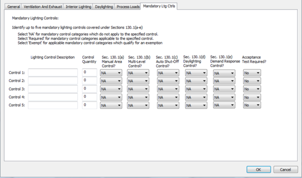
Mandatory Lighting Controls
Figure 55 – Mandatory Lighting Controls
Input summary for the Mandatory Lighting Controls tab:
· Lighting Control Description : A description of the mandatory lighting control in a space, subject to the requirements of Standards, Section 130.1.
· Control Quantity : The quantity of each mandatory lighting control type present in a space, subject to the requirements of Standards, Section 130.1.
· Sec. 130.1(a) Manual Area Control? : Select NA, Required, or Exempt to indicate whether the control is a mandatory manual area control.
· Sec. 130.1(b) Multi-Level Control ?: Select NA, Required, or Exempt to indicate whether the lighting control is a multi-level control.
· Sec. 130.1(b) Auto Shut-Off Control? : Select NA, Required, or Exempt to indicate whether the control is an auto shut-off control.
· Sec. 130.1(b) Daylighting Control? : Select NA, Required, or Exempt to indicate whether the control is a daylighting control.
· Sec. 130.1(e) Demand Response Control? : Select NA, Required, or Exempt to indicate whether the control is a demand responsive control.
· Acceptance Test Required?: Select NA, Required, or Exempt to indicate whether acceptance testing is required for the lighting control.
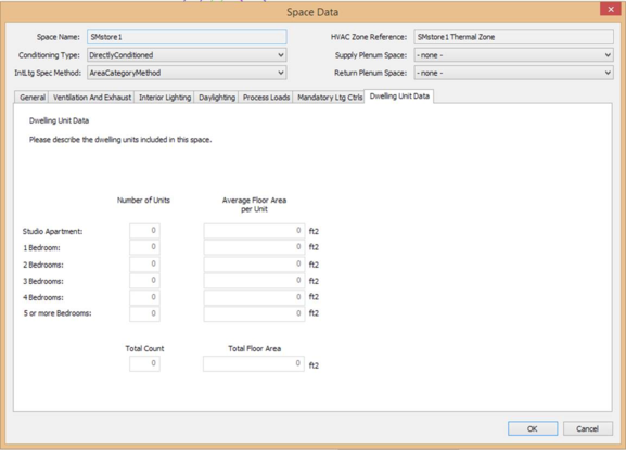
Dwelling Unit Data Tab
Figure 56: Dwelling Unit Data Tab
· Studio Apartment (Number of Units) : Number of studio apartment units in the active space.
· Studio Apartment (Average Floor Area per Unit): Average floor area of studio apartments in the active space.
· 1 Bedroom (Number of Units): Number of one bedroom units in the active space.
· 1 Bedroom (Average Floor Area per Unit): Average floor area of one bedroom units in the active space.
· 2 Bedroom (Number of Units): Number of two bedroom units in the active space.
· 2 Bedroom (Average Floor Area per Unit): Average area of two bedroom units in the active space.
· 3 Bedroom (Number of Units): Number of three bedroom units in the active space.
· 3 Bedroom (Average Floor Area per Unit): Average area of three bedroom units in the active space.
· 4 Bedroom (Number of Units): Number of four bedroom units in the active space.
· 4 Bedroom (Average Floor Area per Unit): Average area of four bedroom units in the active space.
· 5 Bedroom (Number of Units): Number of five bedroom units in the active space.
· 5 Bedroom (Average Floor Area per Unit): Average area of five bedroom units in the active space
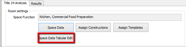
Space Data Tabular Edit
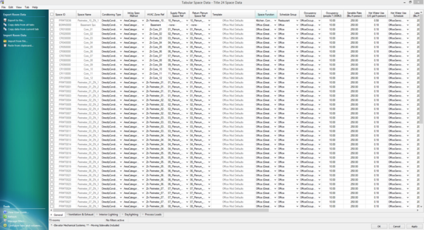
Space Data Tabular Edit is available to input Space Data for multiple rooms. This uses the Tabular Edit interface, similar to that of an excel grid interface. This significant decreases the time taken to input Space Data. All Space Data input is available via the Tabular Edit interface.
Figure 57 – Space Data Tabular Edit button
Figure 58 – Space Data Tabular Edit Interface
Define luminaires
To define a luminaire, click the “Define luminaires” button ( Figure 59 ).
Figure 59 – Define Luminaires button
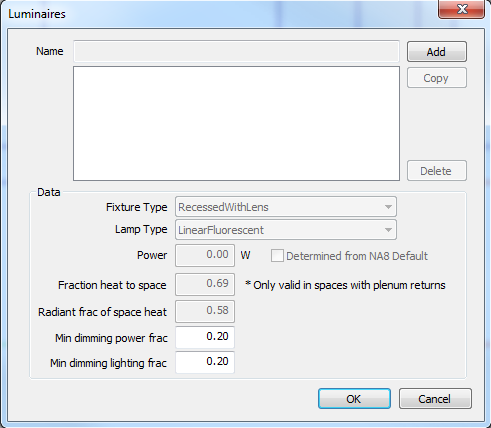
Figure 60 – Luminaires dialog
Input summary for Luminaires:
· Name : The name of the selected luminaire
· Fixture Type : Select the Luminaire’s fixture type. Options are RecessedWithLens, RecessedOrDownlight, NotInCeiling.
· Lamp Type : Select the lamp type used in the luminaire. Options are LinearFluorescent, CFL, Incandescent, LED, MetalHalide, MercuryVapor, HighPressureSodium.
· Luminaire Power : Luminaire power, the connected power for a luminaire including lamp and ballast.
· Determined from NA8 Default (check box): Select for lamp power determined from NA8 defaults.
· Fraction of Heat to Space: Fraction of luminaire heat gain going to space air.
· Radiant Fraction of Space Heat: Fraction of luminaire radiant heat gain going to space surfaces.
· Min. Dimming Power Fraction: The minimum power fraction when controlled lighting is fully dimmed.
· Min. Dimming Light Fraction: The minimum light output of controlled lighting when fully dimmed.
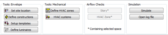
Define HVAC Zones
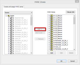
A HVAC zone can be defined using the “Define HVAC zones” button (Figure 61).
Figure 61 – Define HVAC zones button
|
|
|
|
Figure 62 – HVAC Zones
|
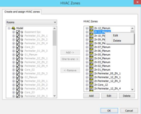
Figure 63 – HVAC Zones right click
|
Upon clicking the “Define HVAC zones” button, the HVAC Zones creation dialog will open (Figure 62). A HVAC zone can be created by clicking “Add”; or by clicking on a room in the left hand window and clicking “One to one ->” in the center of the screen (highlighted in Figure 62). By right clicking on a HVAC Zone and selecting “Edit”, the HVAC Zone Input dialog shall be accessed (Figure 64).
HVAC zones can also be edited through the Tabular HVAC Zone Edit Tool.
The Tabular Edit tool provides an additional feature for replication of Terminal units (see 4.11.2.13) on a zone-by-zone basis within a specific AirSystem, based on an existing ‘Prototype’ serving one zone. This zone is set to ‘Yes’ in the ‘Terminal Unit Prototype’ column of the Tabular edit, and the zones to receive copied Terminal units must be left at ‘No’. Provided all these zones are selected, as illustrated below then, on closing the parent HVAC Zone dialog, additional Terminal units will be generated in the Air System.
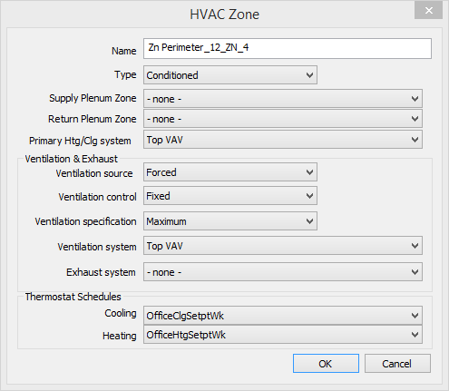
Figure 64 – HVAC Zones Input Dialog
Input summary for the HVAC Zone Input Dialog:
· Name : Name of selected HVAC Zone
· Type : One of a list of categories that characterize the type of conditioning for the space
· Supply Plenum Zone : The name of supply air plenum zone for the current ThermalZone.
· Return Plenum Zone : The name of return air plenum zone for the current ThermalZone.
· Primary Htg/Clg System : The name of the air or zone system that is the principal source of heating and/or cooling for the thermal zone. Only one unique Air System can be assigned to this field
Ventilation & Exhaust section :
· Ventilation Source : The source of ventilation for a thermal zone. Options are NotRequired, Forced, and Natural
· Ventilation Control : The method used to vary the minimum ventilation flow. Ventilation airflow may be fixed at a specified rate or it may be reduced by the use of CO2 sensors or shut off based on an occupancy sensor
· Ventilation Specification : Options are: NoVentilation, Maximum, Sum, FlowPerPerson, FlowPerArea, AirChangesPerHour, and FlowPerZone
· Ventilation System : The name of the air or zone system that provides ventilation air to the thermal zone. This is by default the same system as the primary air conditioning system
· Exhaust System : The name of the air or zone system that exhausts air from the thermal zone. (Input is optional.)
Thermostat Schedules section :
· Cooling : HVAC zone cooling temperature schedule. The schedules specified in Appendix 5.4A and detailed in Appendix 5.4B is used as default
· Heating : HVAC zone heating temperature schedule. The schedules specified in Appendix 5.4A and detailed in Appendix 5.4B is used as default
For the Airflows tab see section 4.12.1.1 .
HVAC Systems
HVAC Systems screen can be accessed using the “HVAC systems” button (Figure 65)
Figure 65 – Systems button
HVAC Systems are divided into four sections:
· Fluid Systems
· Air systems
· Zone Systems
· Recirculation DHW Systems
Fluid Systems
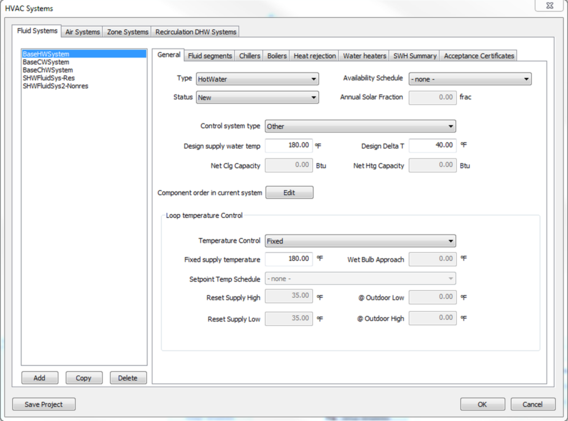
General
The following types of Fluid Systems can be created: Chilled Water, Condenser Water, Hot Water and Service Hot Water
Figure 66 – Fluid System General tab
Input Summary:
· Name : The name of the fluid system.
· Type : Select the type of fluid system. Options are ChilledWater, CondensedWater, HotWater, and ServiceHotWater. The type is used to validate the connections between various FluidSys objects.
· Status : Defines system as New, Existing, or Altered.
· Availability Schedule : The name of the schedule that determines when the hot water system is available to provide heating. The system is not necessarily providing heating at all times it is available, but if it is not available, no heating will be provided
· Annual Solar Fraction : The fraction provided by a certified solar calculator from Go Solar California, applicable for ServiceHotWater fluid system type.
· Control System Type : Select the type of control system used for the fluid system. This is used to specify part load curves for variable speed pumps. Options are DDC or other.
· Design supply water temp : The design supply water temperature of the loop
· Design Delta T : The design supply water temperature delta T.
· Net Clg Capacity/ Net Htg Capacity : The net capacity in Btu of the heating and cooling system
Loop Temperature Control section :
· Temperature Control: The method used to control the chilled water supply temperature. The options are Fixed, Scheduled, OutsideAirReset, WetBulbReset, FixedDualSetpoint, and ScheduledDualSetpoint.
o Fixed means that a constant temperature setpoint is used
o Scheduled means that the temperature is adjusted based on a user specified schedule
o OutsideAirReset means that the water supply temperature is adjusted based on the outdoor air temperature
o WetBulbReset reset means that the water supply temperature is adjusted based on the cooling load
· Fixed Supply Temp (Cooling): The supply water temperature setpoint for 'Fixed' temperature control.
· Fixed Supply Temp (Heating): The supply water temperature setpoint for 'Fixed' temperature control.
· Setpoint Temp Sch (Cooling): The scheduled supply water temperature setpoint of fluid system.
· Setpoint Temp Sch (Heating): The scheduled supply water temperature setpoint of fluid system.
· Reset Supply High: The maximum (high) reset supply water temperature for Temperature Ctrl = OutsideAirReset or LoadReset.
· Reset Supply High (deg. F @ Outdoor Temp): The outdoor air temperature that corresponds to the maximum (high) reset supply water temperature.
· Reset Supply Low: The low supply water temperature used for a reset control. This is the temperature at the high outside air temperature or high cooling load.
· Reset Supply Low (deg. F @ Outdoor Temp): The outdoor air temperature that corresponds to the low supply water temperature used for a reset control.
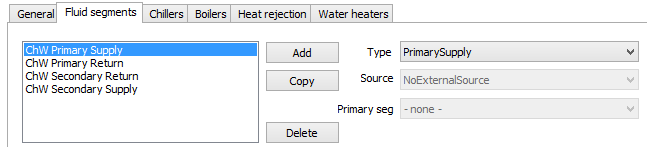
Fluid Segments
Figure 67 – Fluid Segment Input Dialog
Input Summary:
Type: The type of fluid segment. This field is used to validate the connections between various FluidSys objects. Options include PrimarySupply, PrimaryReturn, SecondarySupply, SecondaryReturn, MakeupFluid and Connector.
Source: The source of the Fluid Segment. Available options are No external source and MunicipalWater
Primary Seg: Refers to the segment that supplies fluid to a secondary segment. Applicable to fluid loops subordinate to the primary loop (secondary, tertiary, etc.), this property is used to define the inlet and outlet of secondary segment.
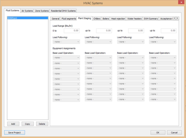
Plant Staging
Figure 68 – Plant Staging tab
· Load Range: Load Range for Chilled water or HotWater plant systems
· Load Following: Chiller/Boiler that will follow after the base loaded equipment
· Base Load Operation: Chillers/Boilers that will be base loaded in each load range
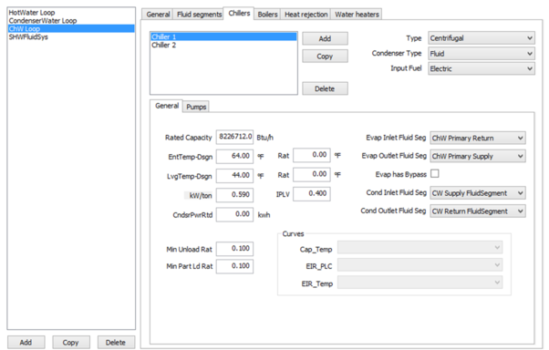
Chillers
Figure 69 – Chiller Input Dialog
Input summary:
· Type : The type of chiller being used based on the compressor type or absorption process. The type of chiller selected from a list: Centrifugal, Reciprocating, Scroll, Screw, Heat Recovery, Heat Pump, Single Effect Absorption, Double Effect Absorption, Triple Effect Absorption. Note that the heat rejection process is not included in the Type descriptor. See Condenser Type
· Condenser Type : Select the method used to reject heat from the chiller. Options are Air and Fluid. Air-cooled chillers use air to cool the condenser coils. Water-cooled chillers use cold water to cool the condenser and additionally need either a cooling tower or a local source of cold water. Evaporatively cooled chillers are similar to air-cooled chillers, except they use a water mist to cool the condenser coil, which makes them more efficient.
· Input Fuel : The form of the primary energy input to the chiller All chillers have a primary energy input along with electricity use for auxiliaries This input describes the form of the primary energy. Options are Electricity, Steam, Hot Water, Natural Gas, or Oil
· Rated Capacity : The cooling capacity of the chiller at rating conditions. The full load output of the chiller operating at rating temperatures and flows
· EntTemp -Dsgn : The chilled water return temperature at design conditions. This temperature is used to size the chilled water components of the system
· ( EntTemp) -Rat : Rated chilled water entering temperature
· LvgTemp -Dsgn : The chilled water supply temperature at design conditions This temperature is used to size the chilled water components of the system
· (LvgTemp) -Rat : Rated chilled water leaving temperature
· kW/ton: The efficiency of water cooled electric chillers in kW/ton.
· IPLV: The integrated part load value (IPLV) value for water cooled electric chillers in kW/ton.
· Min Unload Rat: Minimum unloading ratio.
· Min Part Ld Rat: Minimum part load ratio.
· Evap Inlet Fluid Seg : Name of the fluid segment connected to the evaporator inlet. This is the chiller evaporator inlet connection, to chilled water return.
· Evap Outlet Fluid Seg : Name of the fluid segment connected to the evaporator outlet. The chiller condenser outlet connection, to condenser water return.
· Evap Has Bypass : Whether or not the chiller has Bypass.
· Cond Inlet Fluid Seg : Name of the fluid segment connected to the condenser inlet. This is the chiller condenser inlet connection, to condenser water supply
· Cond Outlet Fluid Seg : Name of the fluid segment connected to the condenser outlet. This is the chiller condenser outlet connection, to condenser water return
Pump Data
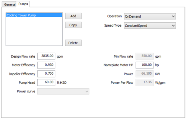
Figure 70 – Pump Data Input Dialog
Input summary:
· Operation : Select how the pump operation is controlled. Options are OnDemand, StandBy, and Scheduled
· Speed Type : Selection allows for constant or variable speed pump
· Status : Options are New and Existing
· Design Flow Rate (gpm) : The capacity of the pump
· Minimum Flow Rate (gpm) : The lowest flow rate available for the pump
· Motor Efficiency : Indicates how well the motor converts electrical power into mechanical power and is defined as output power divided by input power expressed as a ratio
· Impeller Efficiency : Full load efficiency of the pump impeller
· Pump Head (ft H2o) : The pressure head of the pump at design flow conditions
· Min Flow Rate : The lowest flow rate available for the pump
· Nameplate Motor HP : The nameplate horsepower of the pump motor
· Power (kW) : The design power of the pump. This inputs gets calculated by the software based on user inputs for other pump parameters
· Power Per Flow (Ref) (W/gpm) : The power of the pump per unit flow at design flow capacity
· Power curve: The name of the power as a function of PLR curve. This is normally a biquadratic curve
Boiler Data
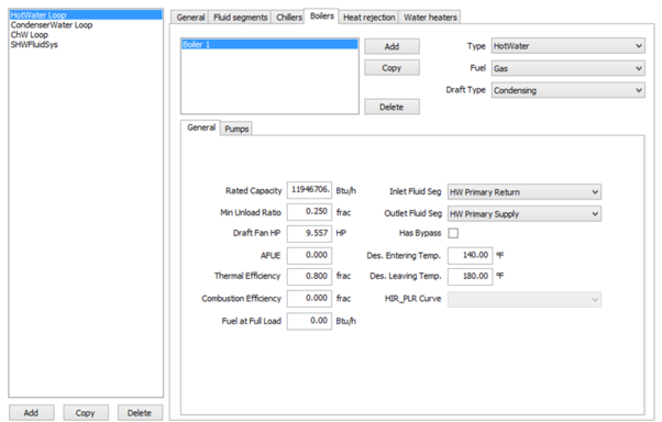
Figure 71 – Boiler Data Input Dialog
Input summary:
· Type : Type of boiler in terms of steam or hot water. Boiler type in terms of fuel used or draft type are defined in other descriptors and rules
· Fuel: The primary fuel used by the boiler to generate heat. Options are gas, oil or electric
· Draft Type : Draft type for fuel fired boilers. Options are MechanicalNoncondensing, Condensing, and Natural
· Rated Capacity (Btu/h): Heat output of the boiler at full load and rated conditions
· Min Unload Ratio (frac) : The minimum load on the boiler at which the boiler can operate without cycling, expressed as a fraction of the full load capacity. At loads less than this, the boiler cycles at the minimum capacity as needed to meet the load
· Draft Fan HP : The nameplate horsepower of the draft fan motor for boilers with mechanical draft
· AFUE : The Annual Fuel Utilization Efficiency of the boiler. Applies only to smaller gas, propane, or oil fired boilers with output heating capacities of less than 300,000 Btu/hr. For larger fuel-fired boilers, use thermal efficiency, and for electric boilers use EIR
· Thermal Efficiency (frac) : The Thermal Efficiency of the boiler. Applies only to larger gas, propane or oil fired boilers with output heating capacities of 300,000 Btu/hr or more. For smaller fuel-fired boilers use AFUE. For electric boilers use EIR
· Combustion Efficiency (frac): The thermal efficiency of the boiler. Applies only to fuel-fired boilers with capacities of more than 2,500,000 Btu/hr.
· Fuel at Full Load (Btu/h) : The fuel consumption at design conditions
· Inlet Fluid Seg: The boiler inlet connection, to hot water return, or HWR
· Outlet Fluid Seg : The boiler outlet connection, to hot water supply, or HWS
· Has Bypass (checkbox): Whether or not the Boiler has Bypass
· Des. Entering Temp : The temperature of the hot water returned to the boiler at design conditions. This may not be the return water temperature during normal operation
· Des. Leaving Temp: The temperature of the hot water supplied by the boiler at design conditions. This may not be the supply water temperature during normal operation
· HIR_PLR Curve : The name of the performance curve which modifies the boiler efficiency (heat input ratio) for the time step as a function of the part load ratio
Heat Rejection
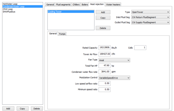
Figure 72 – Heat Rejection Input Dialog
Input summary:
· Type : The type of heat rejection device
o Heat rejection devices include cooling towers and ground source types. The available options are OpenTower and ClosedTower.
· Inlet Fluid Seg : The heat rejection inlet connection, to condenser water return, or CWR
· Outlet Fluid Seg : The heat rejection outlet connection, to condenser water supply, or CWS
· Rated Capacity (Btu/h): The rated cooling capacity at CTI test conditions
o The cooling capacity at rated conditions of 95°F condenser water return, 85°F condenser water supply, and 78°F wet-bulb with a 3 gpm/nominal ton water flow, where a nominal ton is 15,000 Btu/hr
· Cells : The number of cells in the cooling tower. Each cell has its own fan and water flow allowing for responding to lower load conditions. Each cell will be modeled as equal size. Cells are subdivisions of cooling towers into individual cells, each with their own fan and water flow, allowing the cooling system to respond more efficiently to lower load conditions
· Tower Air Flow (cfm) : The rate of air moving through the tower
· Fan Type : The type of fan used in a cooling tower options are axial or centrifugal
· Total Fan HP : The sum of the nameplate rated horsepower (hp) of all fan motors on the cooling tower
· Condenser water flow rate (gpm) : The rate of water flowing through the condenser
· Modulation Control : The method used by the heat rejection device to modulate capacity
· Low Speed Air Flow Ratio : Ratio of the low-speed airflow to full speed airflow. The percentage full load airflow that the tower has at low speed or with the pony motor operating. This is equivalent to the percentage full load capacity when operating at low speed
· Minimum Speed Ratio : Minimum fan speed for a variable speed tower. The minimum fan speed setting of a VSD controlling a cooling tower fan expressed as a ratio of full load speed
Water Heater
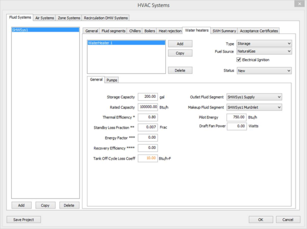
Figure 73 – Water Heater Input Dialog
Input summary:
· Status: The status of the system or component used for additions and alterations. Options areNew and Existing.
· Type: Select the water heater type. Options are Instantaneous and Storage.
· Fuel Source: The water heater fuel source. Options are Electricity, FuelOil#1, NaturalGas and PropaneGas.
· Electrical Ignition (check box): Check this box if the water heater has an electrical ignition.
· Storage Capacity: This is the water heater’s storage capacity.
· Rated Capacity: This is the water heater’s rated capacity.
· Thermal Efficiency: The full load efficiency of a water heater at rated conditions expressed as a dimensionless ratio of output over input. This is also referred to as recovery efficiency.
· Standby Loss Fraction: The tank standby loss coefficient for the water heater.
· Energy Factor: The energy factor (EF) is the ratio of the energy delivered by the water heater divided by the energy used in the same units. The EF is calculated according to 10 CFR Part 430 Test Procedure, which specifies a 24-hour pattern of draws, a storage temperature, inlet water temperature and other test conditions.
· Recovery Efficiency: The water heater recovery efficiency.
· Fluid Segment Outlet: Select the fluid segment outlet. (Input is optional.)
· Fluid Segment Makeup: Select the fluid segment makeup. (Input is optional.)
· Pilot Energy: The water heater’s pilot energy.
· Draft Fan Power: The water heater’s Draft fan power (when Electrical ignition is checked).
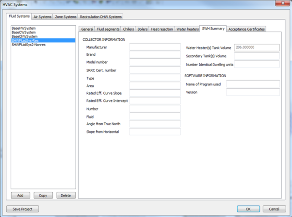
Solar Hot Water (SHW) Summary
Figure 74 – SHW Summary
Input Summary:
· Water Heater(s) Tank Volume: Storage capacities of all water heaters on the fluid system.
· Secondary Tank Volume: Optional input used to populate PRF-01 Table F.
· Number of Identical Dwelling Units: Optional input used to populate PRF-01 Table F.
· Collector Information: Optional input used to populate PRF-01 Table F.
· Software Information: Optional input used to populate PRF-01 Table F.
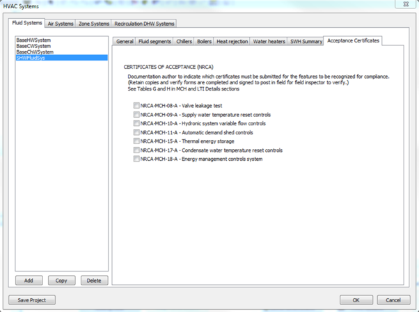
Acceptance Certificates
Figure 75 – Acceptance Certificates
Input Summary:
· Acceptance Certificates: Check Acceptance Certificates indicating whether an acceptance certificate of the number matching the term name is required (used for reporting).
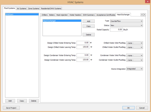
Heat Exchanger
Figure 76 – Heat Exchanger tab
Input Summary:
· Type : The heat exchanger configuration
· Rated Capacity (Btu/h): Design cooling capacity of the waterside economizer heat exchanger
· Status : Defines the HX status as New or Existing.
· Design ChilledWater Entering Temp : Temperature of water entering the HX on the chilled water side of the system at design conditions
· Design ChilledWater Leaving Temp : Temperature of water leaving the HX on the chilled water side of the system at design conditions
· Design Condenser Water Entering Temp : Temperature of water entering the HX on the condenser water side of the system at design conditions
· Design Condenser Water Leaving Temp : Temperature of water leaving the HX on the condenser water side of the system at design consitions
· ChilledWater Inlet FluidSeg : Name of the fluid segment connected to the chiller outlet
· ChilledWater Outlet FluidSeg : Name of the fluid segment connected to the chiller outlet
· Condenser Water Inlet FluidSeg : Name of the fluid segment connected to the condenser outlet
· Condenser Water Outlet FluidSeg : Name of the fluid segment connected to the condenser outlet
· Econo Integration : Integrated or NonIntegrated economizer
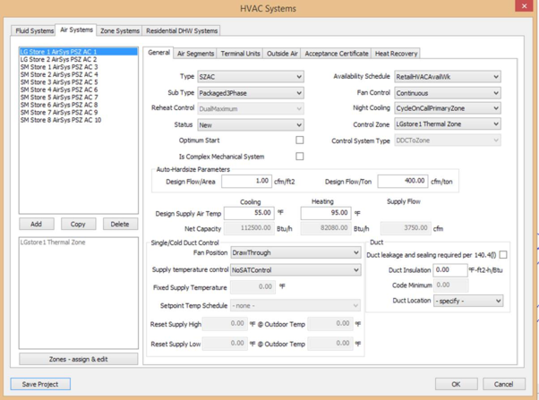
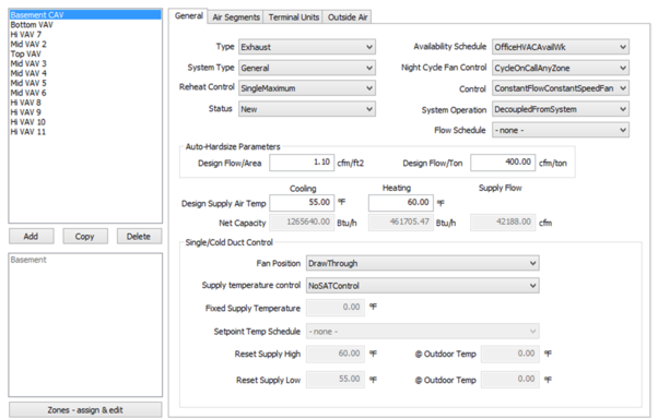
Air Systems
General
Figure 77 – Air System General Tab
Input summary:
· Type : Select the type of air system, a unique descriptor that identifies high level attributes of a HVAC system. Options are PVAV, VAV, SZAC, SZHP, SZVAVAC, SZVAVHP, HV and Exhaust
· Sub Type : Property used to define rating conditions and efficiency requirements of system components. Options available are Packaged3phase, Split3phase, Packaged1phase, Split1phase, CRAC and CRAH
· Reheat Control : The air/temperature control strategy for VAV reheat box in heating mode.
o Single Maximum : The airflow is set to a minimum constant value in both the deadband and heating mode. The minimum airflow septoint is typically 30 to 50 percent of maximum. This control mode typically has a higher minimum airflow than the minimum used in the dual maximum below, resulting in more frequent reheat.
o Dual Maximum : raises the SAT as the first stage of heating, and increases the airflow to the zone as the second stage of heating, as follows:
§ The first stage of heating consists of modulating the zone supply air temperature setpoint up to a maximum setpoint no larger than 95°F while the airflow is maintained at the deadband flow rate.
§ The second stage of heating consists of modulating the airflow rate from the deadband flow rate up to the heating maximum flow rate (50 percent of design flow rate).
· Status : Defines system status as New, Existing, or Altered
· Availability Schedule : Name of the Availability schedule for the Air System
· Fan Control: The type of fan control system used when the system is scheduled to be ‘on’
· Night Cooling : The HVAC system control method when heating, cooling and fan systems are scheduled to be Off. For this control, the space is controlled to the setback or setup temperature only; this control is not equivalent to night purge control. Options include StaysOff, CycleOnCallAnyZone, and CycleZoneFansOnly
· Control Zone : A reference to the Thermal zone name where controls for the Air System are located
· Control System Type : Select the type of control system used for an HVAC system. Applicable to multizone HVAC systems and their related equipment only. This input affects the proposed design system specification for zone level controls, supply air temperature reset controls, ventilation controls and fan and pump static pressure part-load curves. Options are DDCToZone and Other
· Optimum Start (check box) : Select to indicate Optimum start.
· Complex Mechanical System? (per Section 10-102) (check box): Check to indicate whether an HVAC system is Simple or Complex, used for reporting. Complex systems serve multiple zones or use hydronic heating or cooling. Simple systems are all other systems. Single zone air systems are simple, except for any with hot water heating of chilled water cooling. All multizone air systems are complex.
· Auto-Hardsize Parameters Section:
o Design Flow/Area (cfm/ft2): A ratio used to determine airflow capacity of HVAC components when “Auto-Populate Proposed HVAC Capacities” is checked
o Design Flow/Ton (cfm/ton): A ratio used to determine cooling capacity of HVAC components when “Auto-Populate Proposed HVAC Capacities” is checked
· Design Supply Air Temp (Cooling): The design cooling supply air temperature of single duct system or the cold duct of a dual duct system. This is also the control setpoint for Fixed air temperature control.
· Design Supply Air Temp (Heating) : The design heating supply air temperature of single duct system or the hot duct of a dual duct system. This is also the control setpoint for 'Fixed' air temperature control.
· Net Capacity * (Cooling) : Net Capacity of the Cooling System. Reflects capacity of a single system if count is > 1.
· Net Capacity * (Heating) : Net capacity of the Heating System. Reflects capacity of a single system if count is > 1.
· Net Capacity* (Supply Flow): The capacity of the supply fan in cfm. Reflects capacity of a single system if count is > 1.
· Fan Position : The position of the supply fan relative to the cooling coil
· Supply Temperature Control : The method of controlling the supply air temperature of a single duct system, or the cold duct of dual duct system
· Fixed Supply Temp : The temperature of the air being supplied to the space
· Setpoint Temp. Schedule : The scheduled supply air temperature setpoint of a single duct air system, or the scheduled setpoint temperature of the cold duct in a dual duct system
· Reset Supply High : The maximum (high) reset supply air temperature for a single duct system, or for the cold duct of a dual duct system . If supply air temperature is reset based on outside air temperature, specifies the supply air high setpoint to at the outside drybulb low. If supply air temperature is reset based on 'Warmest' zone, specifies the maximum supply air temperature for reset.
· @ Outdoor Temp : The minimum (low) outdoor air temperature at the high reset supply air temperature during cooling. Applicable when cooling supply air temperature is reset based on outside air temperature, specifies the outside drybulb low.
· Reset Supply Low : The minimum (low) reset supply air temperature during cooling. If cooling supply air temperature is reset based on outside air temperature, specifies the supply air low setpoint to at the outside drybulb high. If cooling supply air temperature is reset based on warmest zone, specifies the minimum supply air temperature for reset
· @ Outdoor Temp : The maximum (high) outdoor air temperature at the low reset supply air temperature during cooling. If cooling supply air temperature is reset based on outside air temperature, specifies the supply air low setpoint to at the outside drybulb high
Duct (Input summary):
Note: These inputs are for reporting only and will not impact simulation results.
· Duct Insulation : The duct insulation R-value for reporting
· Duct Location : Duct Location: The duct location (Conditioned, Unconditioned, Other, None) for reporting and mandatory checks only.
· Duct leakage will be field verified per NA1 and NA2: Check box to indicate whether HERS duct leakage testing will be performed per appendix NA2. If duct leakage will not be field verified the project will incur a penalty as per the Standards /ACM.
· Duct leakage and sealing required per 140.4(l): (check box) : Check box to indicate whether HERS duct leakage testing is required, used for reporting. HERS duct leakage testing is required if duct systems: 1. Supply conditioned air to occupiable space from a single zone constant speed system, 2. Serve less the 5,000 ft2 of conditioned floor area, and 3. More than 25% of the total duct system surface area is located in unconditioned space.
Air System (Exhaust)
Figure 78 – Air System (Exhaust) General Tab
Input summary:
· Name : The name of the Exhaust Air System.
· Type : Select the type of air system, a unique descriptor that identifies high level attributes of a HVAC system.
· Status: Defines system status as New, Existing, or Altered.
· System Type : The type of exhaust system. This input is used to default assumptions for system controls and power. Options available are Laboratory, Commercial Kitchen and Parking Garage exhaust systems and can only be assigned to thermal zones comprised of the applicable SpaceFunction categories.
· Control : Control Type for the Exhaust System. Options available are COContol, NoCOControl.
· Availability Schedule : Select the name of the Availability schedule for the Air System.
· System Operation : Describes whether exhaust system availability control is interlocked with the HVAC system availability. For compliance analysis, exhaust fans are assumed to have the same availability schedule as the ThermalZone's ventilation system, but does not night cycle. Options available are DecoupledFromSystem and CoupledFromSystem.
· Flow Schedule : The schedule that defines the flow schedule for the system. This schedule is prescribed for Type = Commercial Kitchen and Laboratory exhaust systems. For General exhaust, the schedule is user defined, but will default to match the HVAC system availability schedule for the ThermalZones that the exhaust system serves. For Parking Garage systems, the schedule is prescribed to be constant, and the fan power is adjusted to account for variable speed fan control.
Air Segment
Figure 79 – Air Segment Input Dialog
Input summary:
· Type: The type of Air Segment. Options are Supply, Return and Relief
· Path: The path of the Air Segment. Options are NotApplicable, Direct, Ducted and PlenumZones