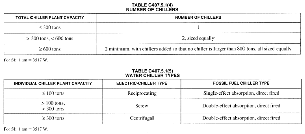
Notes to Table C407.5.1(3) state that the standard reference design's chiller plant shall be modeled with chillers having the number as indicated in Table C407.5.1(4) as a function of standard reference building chiller plant load and type as indicated in Table C407.5.1(5) as a function of individual chiller load. Where chiller fuel source is mixed, the system in the standard reference design shall have chillers with the same fuel types and with capacities having the same proportional capacity as the proposed design's chillers for each fuel type.
For applicable IECC standard reference systems the number and type of electric water-cooled chillers to be modelled is determined as a function of building peak cooling load. When the building peak cooling load is less than or equal to 300 tons, a single screw chiller is required. When the building peak cooling load exceeds 300 tons but is not larger than 600 tons, two equally sized screw chillers are to be used.
For models where the standard reference building peak cooling load exceeds 600 tons, a minimum of 2 equally sized centrifugal chillers must be used. No chiller, however, can be greater than 800 tons so the addition of more equally sized chillers may be required on large projects.
Applicable IECC standard reference systems in ApacheHVAC include a single water-cooled centrifugal chiller by default. For baseline buildings where the peak cooling load does not exceed 300 tons, no additional chillers are needed, but the chiller curve selection will need to be updated to a screw-type chiller.
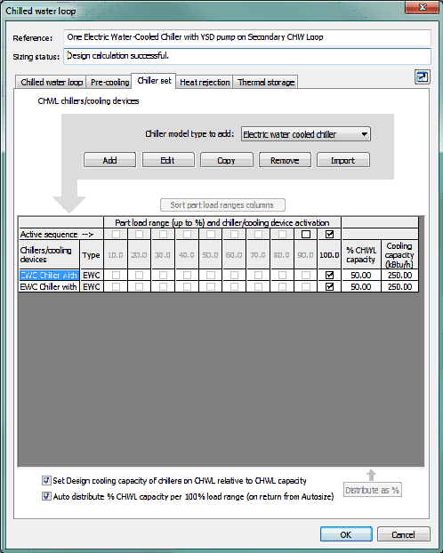
If the peak cooling load in the standard reference building exceeds 300 tons but is not larger than 600 tons, users can add a second chiller to the chilled water loop by using the copy button on the Chiller set tab of the Chilled water loop dialog. Both chillers will need screw curve sets (not the default centrifugal curves) so it is recommended that this change be made prior to using the Copy button. Users should ensure that the chillers are equally sized and can do so quickly by setting the % CHWL capacity to 50% for each chiller.
Figure 8: Chiller set tab of the Chilled water loop dialog illustrating two equally sized chillers serving a peak building cooling load of 500 tons
If the peak cooling load in the baseline building exceeds 600 tons, users can copy the default chiller until there are enough chillers on the chilled water loop to satisfy the building peak cooling load without any chiller exceeding 800 tons in size. Every loop must have at least 2 chillers and all chillers must be equally sized.
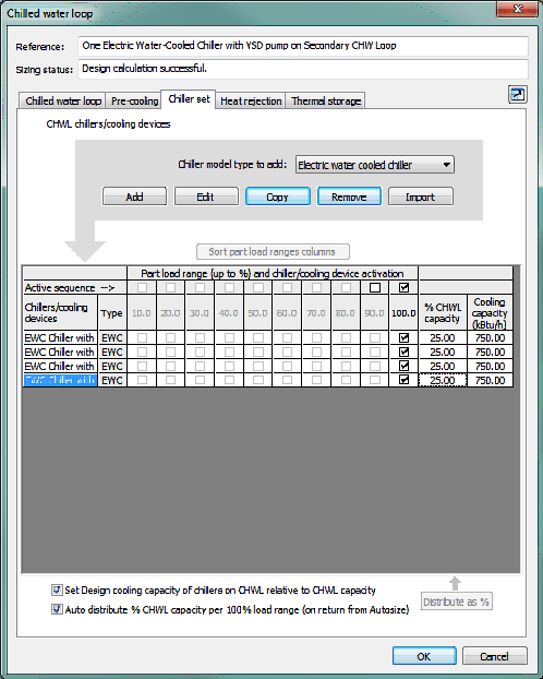
For example, a model where the baseline building peak cooling load is 700 tons requires 2 x 350 ton chillers. Where the standard reference building peak cooling load is 3,000 tons, the model requires 4 x 750 ton chillers.
Figure 9: Chiller set tab of the Chilled water loop dialog illustrating four equally sized chillers serving a peak building cooling load of 3,000 tons
It should be noted that the default baseline chiller curves come from the generic curve sets in DOE-2.2 and are based on entering condenser temperature (ECT). The manufacturer-specific curves available to users in the Performance Curve library are based on leaving condenser temperature (LCT). If LCT curves are used for the proposed chillers, users may consider following the steps below to better isolate the results of actual differences in the baseline and proposed chiller plants (e.g., differences in chiller COP, design sizing, supply water temperature set points, etc.):
· Define appropriate curve set for proposed chiller & test via simulation to confirm that the chiller is modeling as expected.
· Save a copy of that chiller with a new name for the standard reference chiller.
· Revise the COP at the rated condition to match the IECC requirements for minimum chiller performance in Chapter 4.
· Confirm that the IPLV is at least that required for IECC Data needed for IPLV calculations can be found by reading the values at the four required load ranges from the 2D plots in the ApacheHVAC Performance Curves Library interface. Derivation of IPLV for each chiller curve set will be included in a future release of the VE.