3.1.2 Manual editing of HVAC profiles to alter the midband offsets from setpoint and thus modify this aspect of the throttling range
To adjust the control midbands closer to the heating and cooling setpoints, you will need to manually edit the HVAC profiles in the ApPro database.
IMPORTANT NOTE: The System Schedules dialog, which can be a valuable tool prior to manual edits, should not be used to edit or assign edited profiles after manually editing, as this will overwrite manual edits.
As of VE 2012 Feature Pack 1, the System Schedules & Setpoints dialog includes a facility for assigning any alternate set of set-point and HVAC profiles to selected zone groups and/or HVAC systems. To avoid overwriting manual edits, it is essential that you create and assign an alternate profile set before manually editing them to adjust the throttling range, and thereafter ensure that you do not click OK or Apply in the System Schedules dialog when the modified set of profiles is selected. The dialog is not (yet) capable of editing the profiles for any throttling range expect the default, and it will overwrite your manual edits with defaults for this aspect of the profiles if you click either OK or Apply.
For the same reasons, it will also be valuable to use the System Schedules dialog to edit HVAC operating hours, morning start-up, after-hours operation, and control strategy for night/unoccupied operation before manually editing the profiles to reduce throttling range, etc.
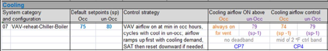
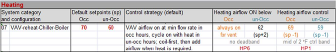
The tables in ApacheHVAC User Guide Appendix B: HVAC zone controller profile values relative to setpoints entered in the System Schedules dialog (above) are helpful in identifying which profiles need to be modified for a particular system type (listed in the first column). The associated profiles are indicated as “HP2, HP5, CP1, CP7” corresponding to the profile names in the ApPro database view. For each system type category (07, 09, etc.), the table indicates in a column for each relevant control the midbands value relative to setpoint, which profiles is used, and whether the value is the middle of a deadband for on/off controls with hysteresis or the midpoint of a proportional control band. The following VAV reheat system rows from the table illustrate this:
For Cooling airflow, for example, the table indicates that…
· The on/off control schedule and setpoint are governed by HVAC profile CP7, which forces the airflow ON during all occupied hours and, depending upon the night/unoccupied control strategy selected by the user in System Schedules, cycles the airflow ON/OFF according to an elevated setpoint value that is 1°F below the Unoccupied Cooling Setpoint. Given the default Unoccupied Cooling Setpoint of 80°F and the selection of Temp setback with HVAC fan cycling as the Setback Strategy, the cooling airflow will be on at no less than the minimum fan flow rate when any one or more zones exceeds 79°F.
· The midband value and setback schedule for this value for proportional cooling airflow control at the VAV box is governed by HVAC profile CP4. This profile has a value 1°F below the Cooling Setpoint for both Occupied and Unoccupied hours. Thus, when the daytime or Occupied Cooling Setpoint is defaulted to 75°F, the proportional control of the zone airflow will use a midband of 74°F.
To reduce the offset of the daytime cooling airflow control with respect to the cooling setpoint, and thus reduce the standard throttling range so that the setpoints can be closer together without overlapping controls, the daytime value in profile CP4 needs to be closer to or even equal to the cooling setpoint.
· If you were to raise the daytime value in profile CP4 in the example above from 74°F to 75°F (equal to the cooling setpoint) without altering the default proportional control bandwidth of 2°F, this would also raise the lower end of the proportional control band by 1°F, thus allowing the heating and cooling setpoints to be 1°F closer together without overlapping controls.
· If you were to raise daytime value in profile CP4 by the same 1°F and also reduce the proportional control bandwidth from the default of 2°F to just 1°F, this would allow the heating and cooling setpoints to be 1.5°F closer together without overlapping controls.
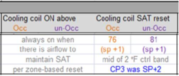
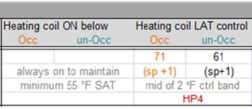
· If you then do the same for the Heating coil LAT control—moving the midband 1°F closer to the setpoint and contracting the proportional band from the default 2°F to just 1°F—you would gain the same 1.5°F of added leeway on the heating end of the control range. With both heating and cooling control bands moved and retracted by this same amount, you would free up 3°F of actual deadband (no control operation other than min airflow) between the setpoints.
· If you then chose to have no actual deadband whatsoever, the modifications described above would permit heating and cooling setpoints separated by just 1°F without overlapping controls. Note, however, that this will tend toward instability as small variations in room temperature will very easily trigger alternating addition of cooing airflow and zone-level reheat. This will drive the model toward shorted simulation time steps, such as 1 to 6 minutes, to avoid modeling excessive energy consumption associated with oscillation between heating and cooling. And, very small simulation time steps will at significantly to the time required to perform an annual simulation. It is therefore highly recommended that for such models, if the project is anything much more than a very small building with very few zones, the majority of diagnostic simulation and testing of hypotheses, etc. should be performed using very short periods of 1 to 3 days in each relevant season—e.g., three very cold winter days, three very hot summer days, and three shoulder-season days.
The user inputs for system setpoints and translation to controller inputs are presently being revised and will eventually include separate heating and cooling user input parameters for Control Throttling Range. This will facilitate modeling unusually tight control of space temperatures without having to manually customize the HVAC profiles as described above.