Miscellaneous Notes
This section contains a series of useful notes; they may contain information which is repeated elsewhere in the documentation.
1. Glare
2. Daylight Factor
3. Sky Component
4. Material Types
Glare
Glare is caused by either or both the following:
1. Excessive luminance values in the field of view.
2. Too high luminance contrasts.
Windows can have a high luminance compared with other luminances in a room. This gives a strong contrast from inside to outside, potentially causing glare. In Radiance simulations we may offset this by providing some internal background lighting. The strongest luminance source is the Sun, and if this in the field of view then glare is inevitable. The default glare threshold is calculated by the program to be 7 times the average luminance level, if required the user can specify an alternative value.
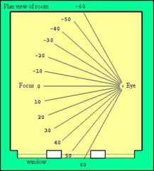
We normally give the CIE Glare Index and the GUTH Visual Comfort Probability (% of people who are satisfied) as measures of glare. These values are calculated at fixed angles to the left and right of the centre of focus (usually at 10 degree intervals from –60 to +60 degrees), see figure below:
Daylight Factor
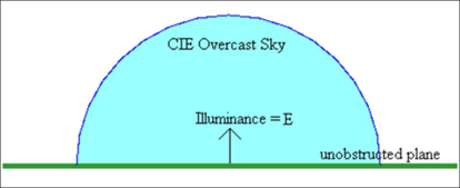
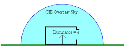
The ratio of the illuminance at a point on a given plane within an interior due to the light received directly and indirectly from a sky of assumed or known luminance distribution, to that on a horizontal plane due to an unobstructed hemisphere of this sky. Direct sunlight is excluded from both values of illuminance (i.e. CIE Overcast Sky).
E = illuminance on unobstructed plane
e = illuminance at point in interior
Daylight Factor = e/E (often expressed as a percentage)
Illuminance is measured in LUX
Sky Component/Vertical Sky Component
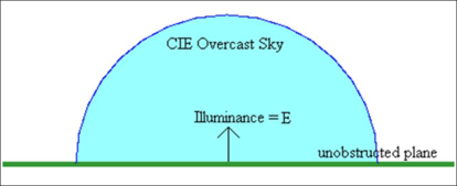
The ratio of the illuminance at a point on a given plane within an interior due to the light received directly from a sky of assumed or known luminance distribution, to that on a horizontal plane due to an unobstructed hemisphere of this sky. Direct sunlight is excluded from both values of illuminance (i.e. CIE Overcast Sky). Note this is the same as the Daylight Factor except the indirect component has been removed.
E = illuminance on unobstructed plane
e = illuminance at point in interior
Sky Component = e/E (often expressed as a percentage)
Vertical Sky Component = v/E
Material Types
Plastic - a plastic surface has a colour associated with diffusely reflected radiation, but the specular component is uncoloured. Most materials fall into this category – painted surfaces, wood, stone, plastic.
Metal - this material type differs from that of plastic in that the specular component is modified by the material colour.
Both these materials have five parameters:
1. Reflectance value for Red, 0.0 – 1.0.
2. Reflectance value for Green, 0.0 – 1.0.
3. Reflectance value for Blue, 0.0 – 1.0.
4. Specularity value, 0.0 - 1.0.
5. Roughness value, 0.0 – 1.0.
The extremes of 0.0 and 1.0 for the reflectance values do not occur in nature. Plastic materials are generally not very reflective and the specularity value is usually in the range 0.0 - 0.07. Metal materials are reflective and the usual range is 0.5 – 1.0. Plastic materials generally have a roughness in the range 0.0 - 0.02. Metal materials have range of 0.0 – 0.5.
There are a number of different material types which can be used for window constructions (dielectric, translucent, glass), with the simplest of these being glass. This is a specially modified dielectric and has a standard refractive index of 1.52 and all that needs to be defined is the transmission at normal incidence.
The glass material has three parameters:
· Transmission value for Red, 0.0 - 1.0.
· Transmission value for Green, 0.0 - 1.0.
· Transmission value for Blue, 0.0 - 1.0.
The dielectric material has five parameters:
· Transmission value for Red, 0.0 - 1.0.
· Transmission value for Green, 0.0 - 1.0.
· Transmission value for Blue, 0.0 - 1.0.
· Refractive Index value, 1.0 – 2.0.
· Hartmann Constant value, -20.0 – 30.0.
The translucent (or trans) material has seven parameters:
· Reflectance value for Red, 0.0 - 1.0.
· Reflectance value for Green, 0.0 - 1.0.
· Reflectance value for Blue, 0.0 - 1.0.
· Specularity value, 0.0 - 1.0.
· Roughness value, 0.0 - 1.0.
· Transmission value, 0.0 - 1.0.
· Transmitted specularity value, 0.0 - 1.0.
Design Tips
Simulation Tips
Design Inertia
When you first look at a design, you have what we call “Design Inertia” (unless you are making it up from your own ideas). This is the initial period when you start to look at the drawings, etc., before you decide how to build the model. Obviously this takes time, dependent on your own experience and the quality of the information you receive. Some planning will be required, but sometimes the best way to tackle this problem is to start to create the model with the understanding that you will have to go back and make changes. Starting with the bits of the model that are easiest to do is an obvious strategy, and by the time you get to the more difficult bits you at least have some context to work with. Radical revisions of a model should perhaps be saved as a new project then you can always go back a step.
Iterate
Never spend a long time creating a model and then expect to get results out at the last minute (i.e. don't spend all week modelling and expect to get the correct results on Friday afternoon). Instead, iterate (design is iterative), do a bit of modelling then try a test simulation or two before refining the model. (This can also be true for most other areas of simulation). These test simulations should be inexpensive (i.e. Low/Medium quality), don’t waste time waiting for a complex simulation, which you are going to throw away once you have refined the model. If you want a more complex simulation use what would be non-productive time to run the simulation i.e. lunchtime or overnight. Test simulations should be tidied up (i.e. deleted) when you have an improved simulation.
Virtual Camera
It is important to understand that in Radiance we are simulating using a virtual camera and not trying to model the eye. This is why we often use the term photorealistic simulation (the eye is a very complex instrument compared to a camera).
Design Day(s)/ Design Time(s)
The software can perform analyses for any given date/time, so the biggest problem is deciding when to simulate and when not to simulate. Sometimes the client will specify exactly what they require, but mostly they will not. The obvious design days are - mid-summer, the 21st June and mid-winter, the 21st December. These will give maximum and minimum levels of daylight. Another popular date is to pick a date half way between - the 21st of September (you should note that although there are slight differences in the Sun's path before and after the 21st June, for design purposes it is treated as symmetrical - this means that design studies are performed between 21st June and 21st December and the other half of the year is ignored, probably because it is easier to think in terms of “June to December” rather than “December to June”).
As well as varying seasonally, daylight also varies daily. East facing rooms will get sunlight in the morning and West facing in the afternoon. The use of Daylight Factors can be useful for reducing the number of simulations (see below). Often you are presenting the worst case scenario, i.e. the minimum Lux, or the maximum glare.
Design Sky
There are a number of different sky types in Radiance, but two are of particular importance - the CIE Overcast Sky and the Sunny Sky. The CIE Overcast Sky is used to give the worst case scenario (in design terms) for illuminance. The Sunny sky is used to give the worst case scenario for glare analysis (luminance images). There are some designers out there who believe that the CIE Overcast Sky has a fixed brightness (they usually quote 10,000 Lux), this is not the case, as the zenith brightness of the CIE Overcast Sky varies by Site Latitude, by season and by the time of the day. There is a mechanism in Radiance to define the zenith brightness, but this has not yet been implemented in the <VE> interface.
Control of Simulations
It is very important to keep control of the simulation files (and other derived files, e.g. Lux contours, DF contours, etc.) you are creating, i.e. making sure the correct design dates/times and skies are used and the files you create are easily identifiable. There is nothing worse than to have twenty simulations with the default naming strategy i.e. “test1”, “test2”, test3”, etc. Favour a naming strategy that identifies the images by using simple mnemonics e.g. “v1_S12_c” - view 1, September, 12 noon, CIE sky, or “v4_D10_s” - view 4, December, 10am, sunny sky. Using this technique I can decode any image by looking at the name. (Note the 21st of the month is implied as the date of the simulation in the above, but may also be part of the mnemonic).
Saving Parameters
When performing a series of simulations, it is important run them with the same accuracy setting, otherwise comparisons are meaningless. If you are using a default setting e.g. “Medium”, this is usually OK, however if the “Customise” option is used it can be difficult to remember exactly what was used when you come back to do more simulations at a later date.
Daylight Factor
When using the CIE Overcast Sky it is possible to generate Daylight Factors, this value (expressed as a percentage) is the ratio of measured illuminance to a theoretical maximum on an unobstructed plane. This ratio is constant whatever the date/time of simulation, thus only one simulation is required to generate this data. See the separate note on Daylight Factors and Sky Components for more information.
Contour Images
Saving lots of these images can clutter the image browser and the subdirectory, since these images can easily be regenerated, they can be thrown away after being saved into a report. The source images should be kept for future re-analysis.
Ground Ambient Value
This is the theoretical maximum Lux value on an unobstructed plane using the CIE Overcast Sky i.e. this is the 100% DF value. Where applicable (CIE Overcast Sky) this value is displayed in the image header.
Exposure
The default exposure is set to an average over the whole image, this can result in images which are either over-exposed or under-exposed with respect to some features which you may be interested in. Change the exposure either up or down as required.
Windows Frame Width
An option is available to edit width of the frame that is applied to windows in Radiance calculations. This is found under RadianceIES menu >> Simulation options on the Window Frames tab. Default option is for Frames to be included and to take a width of 0.1m
Keyboard Options
The following keyboard functions are available:
· Ctrl X – delete selected
· Ctrl A – activate Axonometric view
· Ctrl P – activate Plan view
· Ctrl R – activate Right view
· Ctrl L – activate Left view
· Ctrl F – activate Front view
· Ctrl B – activate Back view
· Ctrl O – open Model
· Ctrl N – new Model
· Ctrl S – save Model
Upgrading pre-VE 2019 models
From VE 2019 onwards, Radiance surface materials are part of the assigned construction for surfaces and openings in the model, rather than being assigned as separate entities in their own right. As a result of this, special handling is in place when upgrading older (VE 2018 and earlier) models to migrate the previous separate Radiance surface materials into the assigned constructions.
- Where a construction was assigned to one or more surfaces/openings but each of these used the same Radiance surface material values, the assigned material settings will be directly migrated to the construction.
- Where a construction was assigned to multiple surfaces/openings that used different Radiance surface material values, separate copies of the construction will be automatically created and assigned in order to migrate the assigned material settings appropriately.
- In both situations above for glazed constructions, the Derive from Visible light normal transmittance (Tvis) option will be switched off.
- Where a construction existed but was not in use in the model, the default Radiance surface materials for the construction type will be automatically created for it. For glazed constructions, the Derive from Visible light normal transmittance (Tvis) option will be switched on.
- Where a Radiance surface material existed but was not in use in the model, this will NOT be included after upgrade.
- All component materials and all defined modifiers (patterns, images and BSDFs) should be maintained and available after upgrade.
Any modifier assignment that was applied to an active Radiance surface material in the model should continue to be active for that material following migration to the appropriate construction(s).
Radiance Publications
Grynberg, A. ‘Validation of Radiance’, Lawrence Berkeley Group, July 1989.
Ward, G., “A Contrast-Based Scalefactor for Luminance Display”, Graphics Gems IV, Edited by Paul Heckbert, Academic Press 1994.
Ward, G., “Measuring and Modeling Anisotropic Reflection”, Computer Graphics, Chicago, July 1992.
Ward, G., “The Radiance Lighting Simulation System”, Global Illumination, Siggraph '92 Course Notes, organized by Paul Heckbert, July 1992.
Ward, G., F. Rubinstein, R. Clear, “A Ray Tracing Solution for Diffuse Interreflection”, Computer Graphics, Vol. 22, No. 4, August 1988.