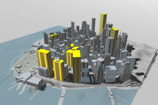
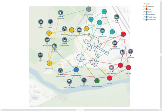
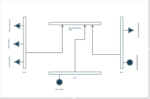
Workspaces within iVN include: 3D model viewer (Figure 3-23), 2D iVN (level 1) viewer (Figure 3-24) and the 2D infrastructure (level 2) viewer (previously known as bus-branch viewer) (Figure 3-26).
Within the 3D model viewer visual settings can be adjusted via the Data inspector; shadows, terrain, map image etc.
Figure 3-23: 3D model view workspace
The 2D iVN (Level 1) viewer includes 2 display modes; Schematic and Geographical, accessible via the view tab (see Figure 3 4).
Figure 3-24: 2D iVN (Level 1) viewer - Workspace
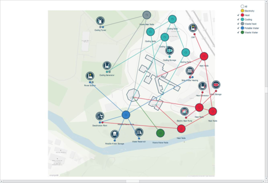
The visibility of networks can be toggled on-off within the 2D iVN (Level 1) viewer networks. Figure 3-25 is an example of the electricity network hidden from the viewer. Hidden networks still form part of a network simulation.
Figure 3-25: 2D iVN (Level) Viewer - Electricity hidden from the Network viewer workspace
The 2D infrastructure (Level 2) view consists of a slack bus, connector bus(es), branch(es), demand(s) and load(s).
The 2D infrastructure (Level 2) view includes a number of features; rotation of buses via right-click, reposition of branches vertically and horizontally.
Figure 3-26: 2D infrastructure (Level 2) view – Workspace
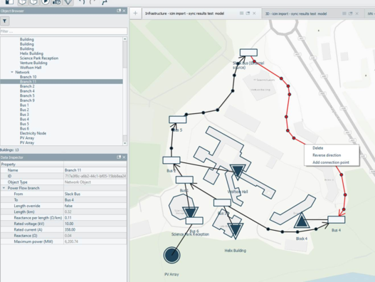
Within the geographical layout of the 2D infrastructure (Level 2) view branch lines between buses are initially represented as straight lines. A user can via a right click menu shortcut on a branch ‘Add connection point’ change the branch from a straight line to polyline.
The branch length, by default, is derived from the geographical layout of the 2D infrastructure (Level 2) view. The user has the option in the data inspector to manually override the branch length. The branch length is used to derive the reactance value of the branch.
Figure 27: 2D infrastructure (Level 2) view – Branch ‘Add connection point’