Spray Chamber / Wetted Media – Evaporative Cooler
The spray chamber/wetted media component provides several different means of modeling an evaporative cooler. It is assumed to follow an adiabatic saturation process with an efficiency that may either be fixed or determined via various methods. The efficiency defines the ratio between the actual moisture take-up of the air relative to the maximum possible (i.e., from on-coil air condition to the saturated condition at the same enthalpy). This can also be thought of as saturation effectiveness, or how close the unit is able to come to providing fully saturated air. It can be set as a constant value, modulated between minimum and maximum values via a profile (e.g., reflecting seasonal variability) airflow rate, pad thickness, and pad face velocity, and can be found in manufacturer's data. Saturation efficiency can also be affected by fan speed.

Toolbar button for placement of a spray chamber / wetted media – evaporative cooler

Spray chamber / wetted media – evaporative cooler component
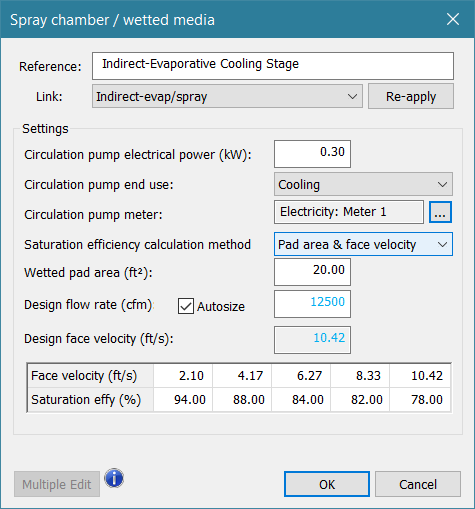
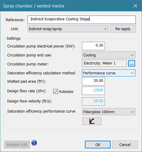
Figure 4-17: Spray chamber / wetted media dialog
This component responds to the following controlled variables:
· Dewpoint temperature at component outlet node
· Relative humidity at component outlet node
· Moisture input or rate of moisture addition at component outlet node
Typical sensed variables within the controller can include, but are not limited to:
· Dry-bulb temperature at sensed node (e.g., conditioned space or supply air temperature)
· Wet-bulb depression at sensed node (i.e., dry-bulb temp minus wet-bulb temp)
Reference
Enter a brief name or description for the component. The reference is limited to 100 characters. It is for your use when selecting, organizing, and referencing any component or controllers within other component and controller dialogs and in the component browser tree. These references can be valuable in organizing and navigating the system and when the system model is later re-used on another project or passed on to another modeler. Reference names should therefore be informative with respect to differentiating similar equipment, components, and controllers.
Link
This value links settings within the System Parameters dialog to the Spray chamber / wetted media evaporative cooler component.
· For direct evaporative cooling, which cools the supply air by adding moisture to it, a pre-defined prototype system will have this component located within the supply airstream.
· For indirect evaporative cooling, the supply air is cooled via heat exchange with an adjacent, non-mixing airstream, such as the system exhaust, that is directly cooled by evaporation. To maintain separation of the directly cooled building exhaust (or similar) and indirectly cooled supply air, heat transfer is provided by an air-to-air heat exchanger. Its location is typically similar to an exhaust-air heat recovery application.
· When adding it to a system or setting up a custom system configuration, it is up to the user to place and control the Spray chamber / wetted media evaporative cooler component accordingly (the link selection alone will not determine direct vs. indirect cooling).
Circulation Pump Electrical Power
If modeling a spray chamber, a pump will normally need to be modeled to account for the added water pressure needed for the sprayer. This pump is assumed to operate whenever the spray humidifier is operating. For some wetted media, the water may be drawn into the pad or media by wicking action, in other cases a pump will be included for this as well. Users should consult technical documentation for the equipment they are modeling.
|
Typical range (kW)
|
0.0 to 15.0
|
|
Error Limits (kW)
|
0.0 to 99.0
|
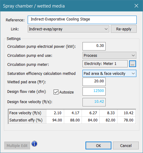
Circulation Pump End-Use
This is the energy end-use to which the spray pump energy consumption will be assigned. Options are cooling, process, and pumps.
Circulation Pump Meter
This is the name of the electricity meter that will tabulate the energy consumption of the circulation pump for the spray component.
Saturation Efficiency
The spray chamber is assumed to follow an adiabatic saturation process. The efficiency defines the ratio between actual moisture addition to the air passing through the unit and the maximum possible (i.e., from on-coil air condition to the saturated condition at the same enthalpy). This can also be thought of as saturation effectiveness, or the relative capability for approaching or achieving fully saturated leaving air.
|
Typical range (%)
|
50.0 to 99.0
|
|
Error Limits (%)
|
5.0 to 100.0
|
Saturation efficiency calculation method
Saturation Efficiency may be determined in one of four methods, as described below.
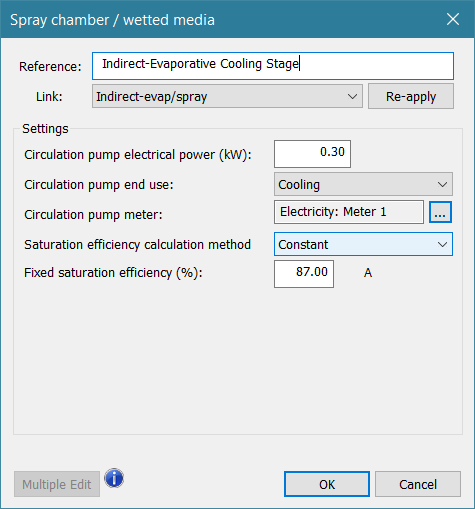
Constant Efficiency – Fixed value
Saturation efficiency is entered as a fixed percentage (0-100%).
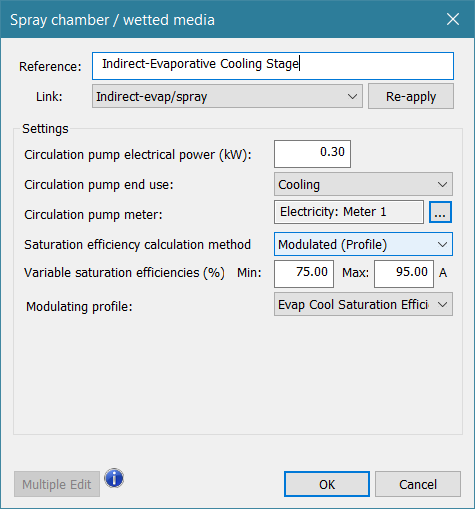
Modulated Efficiency
The Saturation efficiency modulates between entered Min and Max percentages (limits 5-100%), based on the selected modulating profile. A modulating profile value of 0.0 will cause the Min Saturation Efficiency to be used, and a profile value of 1.0 will cause the Max Saturation Efficiency to be used. The profile can contain a formula and references to indoor (room) and outdoor (weather) variables to determine the modulating value, and differing weekly profiles can be nested in a seasonal profile to represent seasonal variations in evaporative cooling performance.
The Max value for Saturation efficiency in the Modulated (Profile) method is also the value that will be updated (via the System Parameter Link for “Direct evap/spray” vs. “Indirect evap/spray”) by any user edits of the associated values within the System Parameters dialog.
Pad Area and Face Velocity – Lookup Table
The saturation efficiency, as a function of the fixed wetted media or pad area and variable airflow rate, is determined by values in a lookup table.
Up to five pairs of Saturation efficiency versus Face velocity are entered. This also requires entry of the Wetted media or pad area, which is used to compute the face velocity during simulation.
Based on the values for Wetted pad area and Design flow rate, the program will also compute the Design face velocity. When the Autosize checkbox is ticked, Design flow rate will be updated with the maximum volume flow rate seen by the component during the System Loads and Sizing run; however, this is for user information only, and does not update the Face velocity values within the table.
All ten values within the table must be manually entered. As the program has no way to know how the user intends for these to be related to the design value, which is really just a point of reference for the user, they are not updated by the system sizing run, and must be manually updated to accommodate changes in the system design airflow.
When, during simulation, the face velocity calculated from volume flow rate and pad area falls between the five user-entered values in the table, the software uses linear interpolation to determine the Saturation efficiency associated with the face velocity for the current time step.
Performance Curve
The saturation efficiency, as a function of the fixed wetted media or pad area and variable airflow rate, is determined by a performance curve.
Use the Saturation efficiency performance curve drop-down to select one of several library curves for saturation efficiency versus face velocity, with efficiency computed based on volume airflow and pad area. Curves are listed in terms of their pad material and thickness.
Wetted media or spray pad area must also be entered, as this is used to compute the face velocity during simulation.
Entering Design flow rate updates the derived value for Design face velocity. This provides necessary information regarding the applicability of the performance curves method.
· A face velocity within the applicable range for the library performance curves is necessary to achieve realistic results for evaporative cooling performance.
· The pad area and design flow rate must result in a design face velocity less than or equal to the upper bound of the applicable range, which is 5 m/s (16.4 ft/s).
· If the applicable range is exceeded, and assuming the design flow rate is consistent with that expected for the system, firstly consult manufacturer data to ensure that the higher face velocity is appropriate. If not, use a larger pad area to reduce the face velocity.
· If a face velocity substantially greater than 5 m/s is required, it is advisable to switch to the Pad Area and Face Velocity – Lookup Table method.
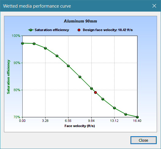
A curve plot button is provided to display the selected curve:
Design flow rate
The Design flow rate is an editable input is used to calculate the Design face velocity. These values are for user reference when entering values in the lookup table for the Pad Area and Face Velocity method or when selecting a pre-defined curve under the Performance Curve method.
Design face velocity
The derived Design face velocity is for user reference when entering face velocity values in the lookup table for the Pad Area and Face Velocity method or when selecting a pre-defined curve under the Performance Curve method.
Autosize checkbox
When checked, the Design flow rate will be set to the maximum flow through the component during the system-level sizing run. The derived Design face velocity will be revised accordingly.
As autosizing of the flow rate and pad area have not yet been implemented for this component, it is up to the user to ensure that the face velocity values entered within the lookup table or selection of performance curves is consistent with the design flow rate entered or autosized during the system sizing run.