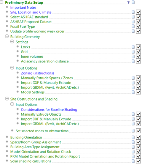
The preliminary section of the navigator contains actions that allow users to, for example, set site location and climate, import prototype data, create geometry, set building orientation and room grouping, etc.
Important notes
If applicable this hyperlink provides access to any high level information that may be important for the user to understand before using a specific version of the navigator
Site, Location and Climate
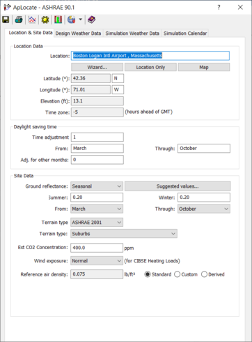
This action opens the ApLocate sub-program from which the user then specifies the global location of the building (Lat.>Lon.), external design conditions and simulation weather file. This process is driven by clicking on the ‘Selection Wizard...’ and following the necessary steps:
There are four tabs associated with this dialog box:
• Location & Site Data – there are two options for selecting (Selection Wizard or Set Location Only) the climate file associated with the project.
• Design Weather Data – provides feedback on the climate selected and the ability to review and customize key parameters of the climate selected. This data will be used for the Sizing Runs.
• Simulation Weather Data – Reports the weather file that ApacheSim will be utilizing for simulation runs. The file is selected based on the choices within Location & Site Data/Selection Wizard, however the user can also change the selection within this tab to browse and select a different weather file. This data will be used for the annual thermal/energy simulations.
• Simulation Calendar – provides the ability to select and customize ‘a holiday template’ (days considered to be holidays which could trigger different building operation setting) based on the country and other parameters.
Once the location is selected the climate file, which provides the input data for the hourly energy (8,760 hours) is determined. The VE actually runs the energy analysis on 6-minute time steps (as a default) versus hourly, so that the influence of thermal mass can be accounted for within the design.
Select ASHRAE Standard
The ASHRAE 90.1 navigators caters to both the Performance Rating Method and the Energy Cost Budget method. This action allows the user to select the appropriate method which will then be followed throughout the navigator.
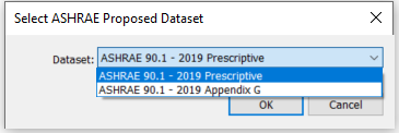
ASHRAE Proposed Dataset
This action imports an ASHRAE 90.1 dataset appropriate to the navigator in use and is used as a starting point for population of the proposed model.
From 90.1 2016 onwards two datasets are avilable:
• Perscriptive – this is the data contained within the standard itself e.g. constrructions from Table 5.5
• Appendix G – this is the data contained within Appendix G e.g. constructions from Table G3.4
When the ECB method is chosen only the perscriptive dataset is available to import as Appendix G does not apply to ECB.
When the action is selected the software automatically imports the ASHRAE data in a fully functional VE format. The data includes:
o ASHRAE 90.1 Internal Gains (Occupancy, Lighting, Equipment)
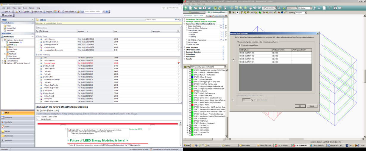
o ASHRAE 90.1 Lighting power densities
o ASHRAE 62.1 Occupancy densities
o ASHRAE 90.1 Profiles/Schedules (from the User’s manual)
o ASHRAE 62.1 Outdoor fresh air rates
o ASHRAE 90.1 Envelope/Fabric Data (ASHRAE Climate Zone specific)
All of these defaults are editable to suit the actual project through subsequent steps of the navigator.
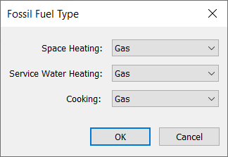
Fossil Fuel Type
All miscellaneous fuel codes are assumed to be electricity except for:
• Space Heating
• Service Water Heating
• Cooking
This command allows the user to select the appropriate fuel type per energy use which will be subsequently used in the automatic generation of ASHRAE 90.1 results reportage in the Results section of the Navigator. This step is only important if these energy end uses are served by fossil fuels. If they are served by electricity and assigned the appropriate fuel code, this step is not necessary.
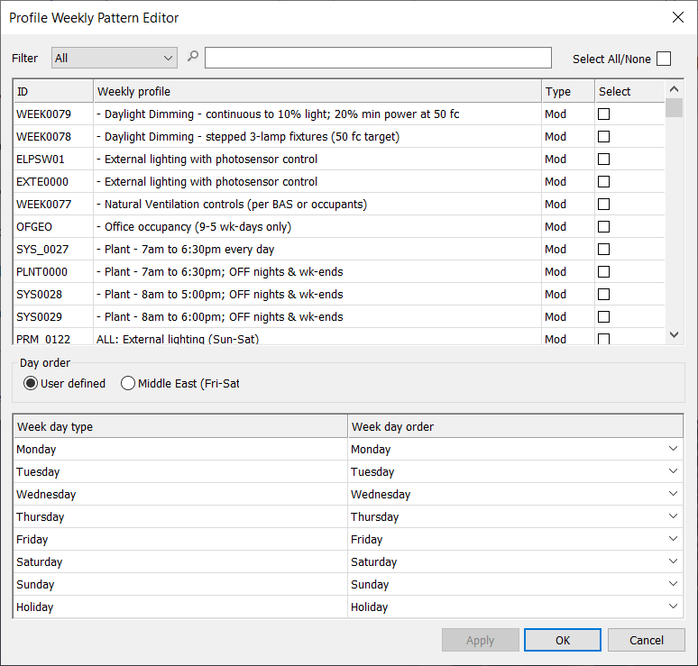
Update Profile Working Week Order
This action takes the user to the ‘Profile Weekly Pattern Editor’ which is used to dictate the daily operation of the building at a daily/weekly level. It allows the user to customize the operational days of their building to match the project requirements.
For example, in the Middle East region the typical working week is Sun-Thu with Fri/Sat being the weekend. In the UK/US however the working week is Mon-Fri with Sat/Sun being the weekend. This dialog allows the user to customize the weekly operation of their building.
An on/off filter is included which allows the weekday order re-shuffle/override to only be assigned to selected Profiles. The ‘All’ check-box allows a quick toggle to turn the entire list of profiles on/off.
Building Geometry
Settings
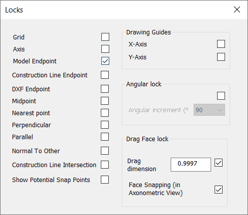
Locks
Locks allow the user to snap the drawing tool to various items in the model view window such as model endpoint, midpoint, grid, etc. When creating model geometry it is useful to have the lock window open so you can switch different locks on and off depending on the particular modeling task you are trying to perform.
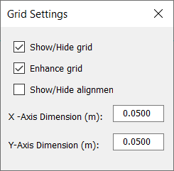
Grid
Snapping to the grid when building model geometry ensures the creation of an accurate compact model which enhances accuracy and performance later in the analysis. This option allows the distance between grid points to be set - in both the x and y direction. Checking the grid box in the locks menu will force the drawing tool to snap to the grid. In general it is recommended to use a grid separation distance of 4 inches (0.1m).
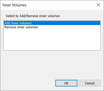
Inner Volumes
This option allows the user to add or remove inner volumes from your model.
Inner volumes are used to take account of the thickness of walls, ceilings and floors. The thickness of the walls will be defined later in the Apache Constructions Database. The thickness of the wall is represented in the model by a grey line which is offset into the room by the thickness of the wall. Inner volumes are only suitable for use in models with relatively simple geometry.
Adjacency Separation Distance
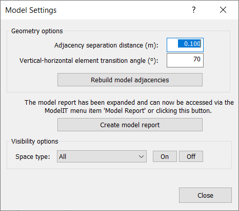
This command opens the model settings window. Adjacency separation distance defines the maximum distance that two surfaces can be away from each other, while still being recognized by the software as being adjacent.
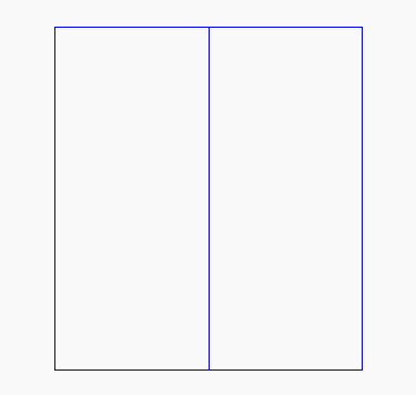
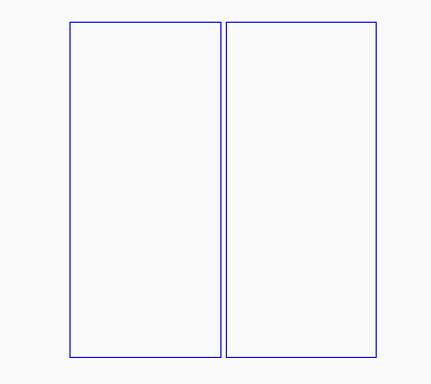
For example the two rooms in the image below on the right are 0.1m meter apart so the software would recognize them as being adjacent. Although in theory this is fine, in complex models it can cause errors to occur. It is recommended to always snap directly to the surface of the adjacent room as shown in figure below on the left. This can be done easily by using the ‘Model Endpoint’ lock.
Input Options
Zoning (instructions)
Zoning is of critical importance to the model. Too many zones and the model becomes overly complex, too few and detail is lost. Although the main focus should be on capturing core functional spaces e.g. offices in commercial buildings or living rooms, bedrooms etc. in residential buildings - it is also necessary to capture the area/volume of other miscellaneous/ancillary spaces such as elevator shafts, toilets, stairs etc.
The single most important aspect to note in relation to these space types is that they do not have to be represented exactly and individually to effectively convey the energy consumption of the building. In other words it is not necessary to model each and every space separately but instead zones can be outlined around each of these space types that capture all of a space type together.
The zoning (thermal block) requirements outlined in ASHRAE 90.1 (proposed model thermal zones and baseline model thermal zones to be the same) should also be kept in mind when creating the building geometry. The details presented should be followed closely in order to meet the requirements of the Performance Rating Method or the Energy Cost Budget Method.
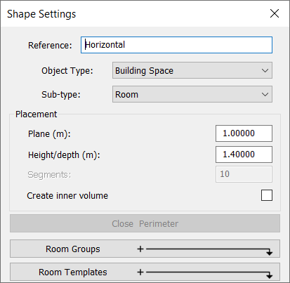
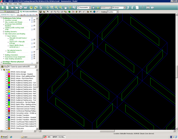
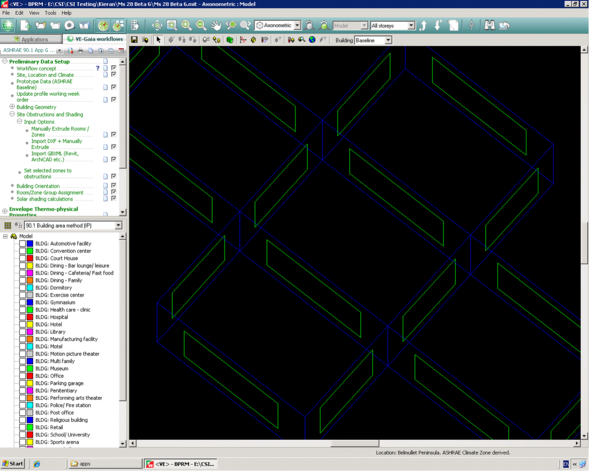
Manually Extrude Rooms/Zones
Click the ‘draw extruded shape’ button and the ‘shape settings’ window will open. Set the height of the room and what plane the room sits on. You can name the room here or you can choose to name the room later by right clicking on it in the room list in the side bar. Draw the outline of a room by clicking on points in the model view window to define the room vertices. It is important to snap to the grid.
Import DXF & Manually Extrude
When importing a dxf it is important to select the correct scale factor. The drawing will appear in grey in the model view window and will sit behind the model. Use this as a guide in which to trace your rooms over while snapping to the grid at all times.
Import GBXML (Revit, ArchiCAD etc)
This action offers an alternative to manually building a model within the <VE> ModelIT module. It allows a .GBXML file to be imported from another CAD platform such as ArchiCAD or other.
Also note that BIM files can be imported through the start page.
Model Settings
The model setting window allows the user to change the adjacency separation distance, vertical-horizontal element transition angle and perform model checks.
Vertical-Horizontal Element Transition angle defines at what angle a wall becomes a ceiling or a floor. By default, if a surface is at an angle less than 60o it is recognized by the software as a ceiling or floor.
The model check option allows you to perform a check on the quality/integrity of the geometry in your model. Check the boxes for intersections and surfaces and click the check button. A text file will be created which will flag up any error in your model geometry. It is recommended to perform model check regularly throughout the model building process. It is usually far easier to fix a geometry problem soon after it occurs rather than at the end.
Clicking the rebuild button refreshes all the adjacencies in the model.
Site Obstructions & Shading
Input Options
Consideration for Baseline Shading
This action brings the user to a webpage explaining considerations for site obstructions and shading specific to that version of the navigator
Manually Extrude Objects
This command has no specific action and simply acts as a prompt giving the user the option of manually extruding shades from scratch. If this is the desired option then the standard ModelIT toolbar should be used to create shades by manually extruding in plan view. When all required shades have been created the Navigator check-box should be ticked confirming that the step has been completed
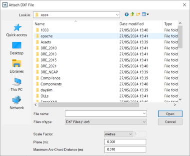
Import DXF & Manually Extrude
This command opens the ‘Import .dxf’ dialog and allows the user to place a .dxf as a trace layer within the ModelIT workspace. The user can then use the standard ModelIT commands to manually extrude shade geometry using the .dxf as a trace layer.
Import GBXML (Revit, ArchiCAD etc)
This command allows 3D .GBXML geometry to be imported directly from another CAD package such as Revit or ArchiCAD.
Set Selected Zones to Obstructions
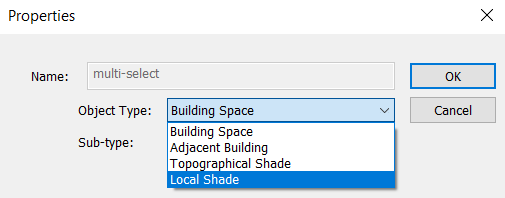
All obstruction zones (i.e. non-thermal zones) should be selected before this action is selected. By subsequently clicking on the Navigator command the following dialog will appear:
The dialog allows the room type to be changed from “Room” to a suitable shading type. There are three types of shading:
• Adjacent Building
• Topographical Shade
• Local Shade
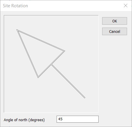
Building Orientation
This option allows the orientation of the building to be set. The arrow points in the direction of north and adjusts when a value is entered on the input line (default position = pointing straight up).
Space/Room Group Assignment
In order to progress through the ASHRAE 90.1 navigator workflow in its intended fashion grouping of rooms becomes a critical step in the overall process. The assignment of thermal templates later on in the navigator relies on the correct grouping of room types. Also the configuration of HVAC systems relies on the early stage grouping of rooms into AHU groups. This step in the navigator may not be applicable to all models as it may be just as easy to manually assign model zones to the relevant prototype grouping schemes.
When the prototype data is imported into the working model, it contains a series of thermal room groups based on ASHRAE 90.1 ‘Building Area’ & ‘Space by Space’ methods. The ‘Building Area’ method is generally used for early stage analysis where the exact function of every zone in the building has not yet been determined. The ‘Space by Space’ method is used more often as it allows the user to assign a particular function to each zone in the building.
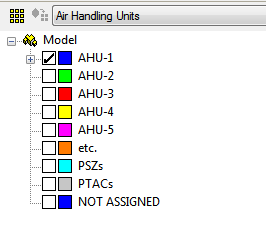
It is advisable to also group rooms in terms of which AHU they are supplied by. This step is not essential but it will make it quicker and easier to assign rooms to their required HVAC systems later on.
The prototype data also contains additional grouping schemes that may be relevant to the users project needs.
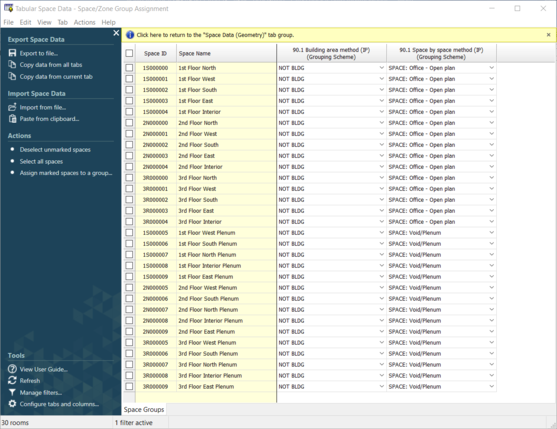
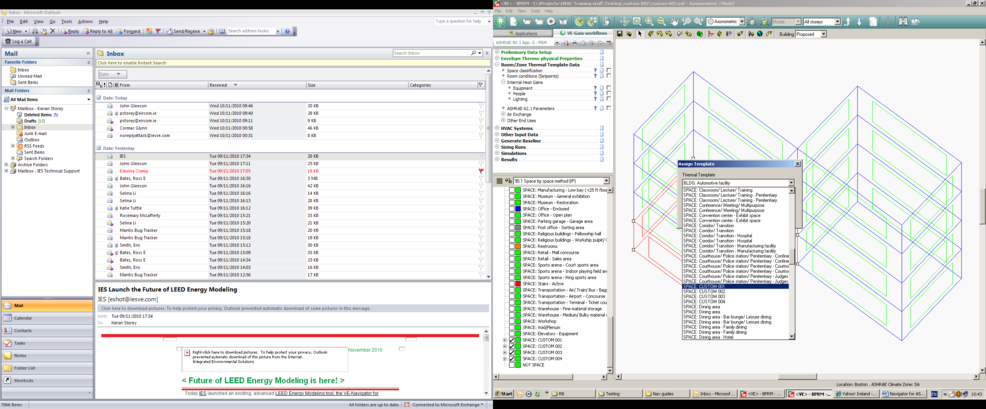
When this action is selected the following tab edit view is displayed:
Here the user can assign building area method or space by space method groupings to groups of spaces or individual spaces. This assignment will then dictate what thermal template is assigned to these spaces later in the navigator via the ‘Space Classification’ action.
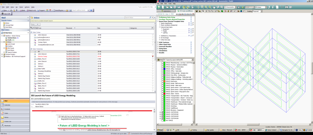
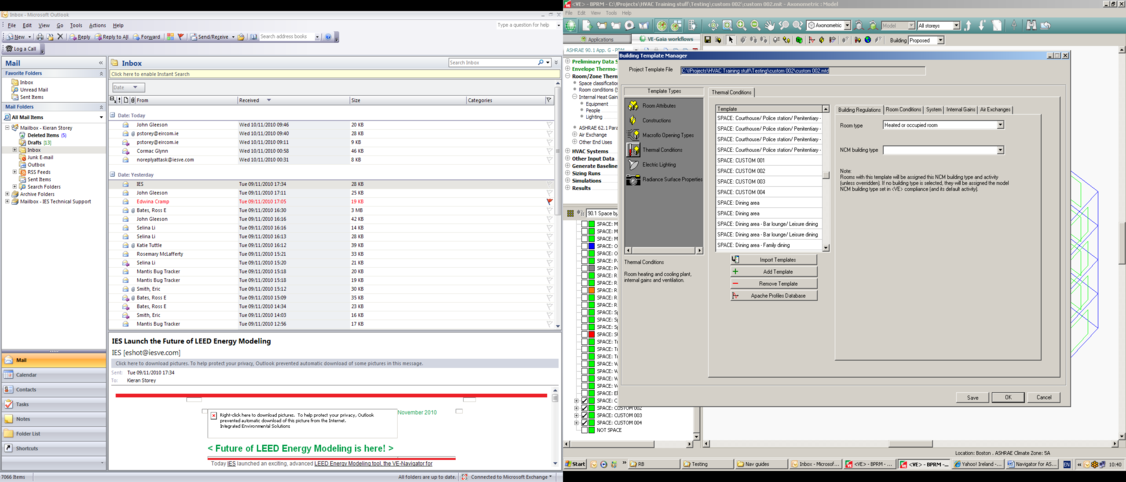
Creating Custom Templates
It may be necessary for users to create project specific custom thermal templates if the Prototype ASHRAE templates do not match all space types in the concerned model. In order to do this users must add additional room groups to the prototype grouping schemes & also create corresponding thermal templates. The group name & thermal template name must match in order for the “space classification” step to work correctly. Custom templates should be created prior to activating the “space classification” command. “Custom” templates must be manually assigned to the custom grouping schemes. See steps below;
1. Add custom groups to ASHRAE 90.1 space by space prototype grouping scheme.
2. Create custom thermal templates in building template manager & setup custom template data i.e. internal gains etc.
3. Manually assign custom created thermals to custom created groups.
4. Once the “space classification” is activated all thermals will be assigned as per there corresponding room group. Once the internal gain “Light” step is activated all custom assigned templates should appear.
Note: Baseline lighting, equipment & occupancy data should be added to the custom made templates as per ASHRAE 90.1 requirements.
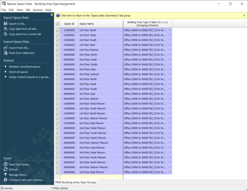
Building Area Type Assignment
In recent ASHRAE 90.1 standards the window to wall ratio used in the generation of the PRM baseline model is dictated by Table G3.1.1-1.
When this action is selected the following tab edit view is displayed.
Here the user can set a building area type for the entire building (all spaces in the building) or for individual / groups of spaces.
Model Orientation and Rotation Check
Depending on the method selected previously (PRM or ECB), this action will react differently.
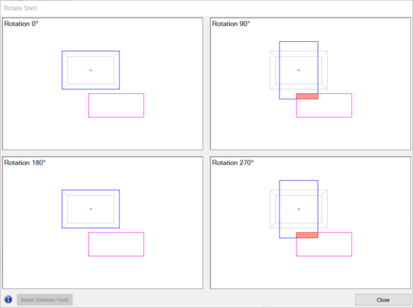
PRM:
The action performs a visual rotation check to determine if, for 4 orientations (0,90,180,270), the building intersects with any spaces of type ‘Adjacent Building’ and indicates where the intersection takes place
If an intersection exists, then the baseline rotations are not required. This is carried on through the navigator.
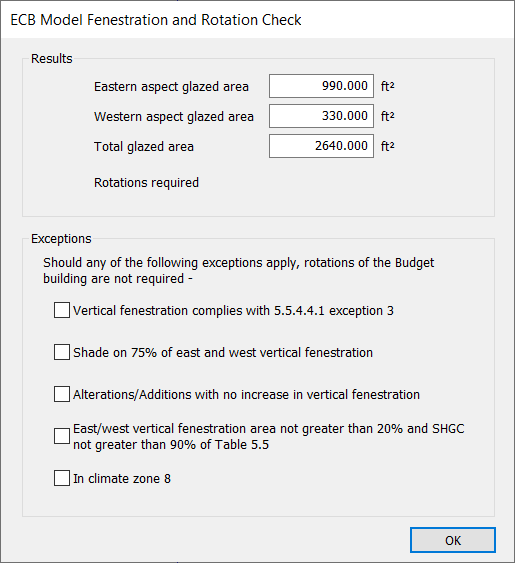
ECB (ASHRAE 90.1 2016 & 2019 Only):
In ASHRAE 90.1 2016 and 2019 a new requirement was added to rotate the budget building under certain circumstances.
When this action is selected, in ECB mode, it determines the eastern, western and total glazed areas and determines whether rotations are required or not.
There are exceptions which override this requirement. These are listed in the dialog that's presented to the user. The user must tick the relevant box if they are to take advantage of any of the exceptions.
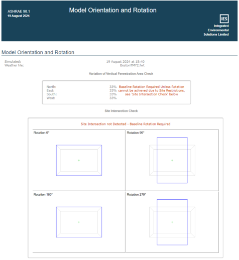
PRM Model Orientation and Rotation Report
The model orientation and rotation report is only applicable when in PRM mode. When selected this action creates a PDF report that details visually the model rotation and reports on whether rotations are required or not. The PDF report is stored in content manager .
Solar Shading Calculation
Clicking this action automatically opens the SunCast module and performs solar shading calculations. Solar shading calculations are performed hour by hour for the 15th day of each month of the year. These results are fed into the Apache Dynamic Thermal Simulation.