Opaque Constructions - Tabs & Ground-Contact Adjustment
Surfaces Tab
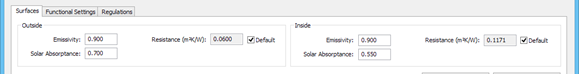
Outside surface:
Emissivity: the emissivity of the outside surface of the construction. Values are provided in Table 23 in the Apache Tables document. Most materials have an emissivity of about 0.9. Lower values apply to unpainted metals.
Resistance: the thermal resistance between the outside surface and its environment. This is the reciprocal of the outside heat transfer coefficient, which is made up of convective and radiative components. Ticking the default box displays a standard value determined from the construction category, together with the Wind exposure in the case of external adjacency. The default value is used in the ApacheCalc programs. In ApacheSim it is replaced by algorithms that take account of the changing heat transfer conditions at every time step. If the default box is not ticked, the entered value is used by all programs.
Solar absorptance: the fraction of incident solar radiation absorbed by the surface. This is a function of the colour and surface finish. Typical values are given in Table 14 in the Apache Tables document or CIBSE Guide A.
Inside surface:
Emissivity: the emissivity of the inside surface of the construction.
Resistance: the thermal resistance between the inside surface and its environment. This is the reciprocal of the inside heat transfer coefficient, which is made up of convective and radiative components. Ticking the default box displays a standard value determined from the construction category. The displayed default value is used in the ApacheCalc programs. In ApacheSim it is replaced by algorithms dependent on simulation options. If the default box is not ticked, the entered value is used by all programs.
Solar absorptance: the fraction of incident solar radiation absorbed by the surface. This is a function of the colour and surface finish. Typical values are given in Table 14 in the Apache Tables document or CIBSE Guide A.
Functional Settings Tab
This tab is only displayed if the construction belongs to the Ground Floor, External Wall or TSC Wall categories.
Ground-contact Floor or Ground-contact Wall: by selecting a method on the combobox, a construction can be identified as a ground-contact floor or wall. The methods for ground contact provided are:
-
-
-
ASHRAE F Factor (floors only)
-
Advanced 2-dimensional (Kiva – walls & floors)
If None is selected no adjustment for ground contact is applied to the construction; users might choose this option for ground contact floors or walls if absolute or scripted profiles (& appropriate surface resistances) are utilised for defining ground temperature.
For the EN-ISO 13370 steady state method it is possible to define floors on-ground level (on-grade), heated basement floors and basement walls. Ground contact slabs can be defined with horizontal or vertical insulation. The following are not covered: suspended floors (section 10), basements beneath part of the building, partially heated or unheated basements, linear heat bridging at the wall base and characterising basement floor & walls in a single effective U value (section 11).
For the ASHRAE F-Factor steady state method it is possible to define floors using ASHRAE F-Factor tabulated data.
For the Advanced 2-dimensional (Kiva) dynamic method it is possible to define floors on-ground level (on-grade), basement floors and fully submerged or partially submerged basement walls including foundation wall / footing geometry / construction, horizontal or vertical insulation and blocks of different materials within the ground that may affect heat flow. This method invokes co-simulation using the KivaTM engine:
-
KIVATM is a foundation heat transfer simulation tool that balances capability, complexity, computational performance, and algorithmic confidence (accuracy within 5%)
-
KIVATM uses a 2D approximation to model 3D heat flow for many floor and foundation arrangements; simple on-grade slabs, on-grade slabs with footings, vertical & horizontal insulation, basements etc.
-
KIVATM models soil, ground water state and boundary conditions using finite difference and has been verified with ASHRAE 140 : 2017. It uses a minimum of soil data inputs
-
KIVATM is the outcome of the Thesis by Neal Kruis and is a requirement of ASHRAE 140: 2017
-
KIVATM is invoked for Apache thermal simulations and ASHRAE loads simulations only
Settings: When a Ground-contact floor/Wall method is selected in the combobox the Settings button may be used to adjust the construction properties to make allowance for the building geometry.
CIBSE uninsulated U-value: For the purposes of Part L2 of the UK Building Regulations, the U-value of an uninsulated floor calculated using the parameters set in the Ground-contact U-value adjustment dialog (accessed via the Adjust button). These parameters must be correctly set for Part L2 analyses. The rules state that where the U-value of an uninsulated floor of the same area and exposed perimeter is less than 0.25 W/m2K, a floor with this U-value must be used in the notional building. If the uninsulated U-value is less than 0.25 W/m2K it will be used to create a bespoke floor construction that will be automatically assigned to the relevant floors in the notional building.
Ground-contact U-value settings dialog (Settings button)
This dialog is accessed via the Settings button on the Functional Settings dialog for exposed floors, external walls and TSC walls which becomes active when a Ground-contact Floor/Wall box method is selected.
The dialog provides a means for adjusting the properties of the construction to make allowance for 3-dimensional heat transfer through the building element and the adjacent soil. The adjustment is a function of building geometry and a set of parameters interfaced on the dialog.
Analysis method: Either the EN-ISO 13370 standard or the ASHRAE F-factor (Heat Loss Coefficient) method may be as the basis of the adjustments. This choice affects the input parameters presented on the dialog.
Parameters and options applying to both methods:
Set ground-contact floor plans: This button invokes the Ground-contact U-value adjustment dialog, which allows the following parameters relating to the building geometry to be set either manually or automatically for each level where a floor is in contact with the ground (use Add level, Insert Level and Delete level):
Level: Assigned automatically to 0, -1, ...
Depth below ground: The depth of the floor surface below ground level
Floor plan area: The total area of ground-contact floor at this level
Floorplan exposed perimeter: The exposed perimeter length of the floorplan at this level
Characteristic dimension: A property of the floor geometry with the dimensions of length, derived automatically as
2 x Floorplan area / Floorplan exposed perimeter
Update from building geometry: This button automatically updates the above parameters from the current building geometry.
Level: Select the level (0, -1, …) to which the construction is to be applied.
Characteristic dimension, Floor depth, Exposed floor perimeter, Floor area: The values of these parameters are copied from the dialog Set ground-contact floor plans. In the case of the first two the values may be overridden after ticking the adjacent box Override for U-value calc?
Note on F-factor method. In the case of floors, the adjusted U-value is calculated to give the correct overall heat transfer coefficient when applied to the entire ground-contact floor area. Users applying the F-factor method may wish to apportion the heat transfer to perimeter rooms only. In this case the Characteristic dimension for the perimeter room floor construction should be calculated as
2 x Perimeter room area / Floorplan exposed perimeter
and a construction with a low U-value should be assigned to non-perimeter rooms.
Apply adjustment?: Tick this box to apply the adjustment to the construction layers on exit from the dialog. An insulating layer will then be added to the construction beneath the soil layer (or if such a layer is already present it will be modified) to achieve the appropriate adjusted U-value.
Parameters applying to EN-ISO 13370 method:
Ground conductivity: The conductivity of the soil. If Copy from layer data? is ticked the value is taken from the soil layer of the construction (when present).
Floor resistance: The combined thermal resistance of the floor layers, excluding the U-value adjustment layer (when present) and any other layers with a conductivity greater than 0.2 W/mK. If Copy from layer data? is ticked the value is derived automatically from the properties of the construction layers.
External wall thickness: The thickness of the external walls of ground-contact spaces.
Edge insulation type: The type of edge insulation (Horizontal, Vertical or None).
Edge insulation width, thickness & conductivity: The width, thickness and conductivity of the edge insulation (where present).
Parameters applying to ASHRAE F-factor (Heat Loss Coefficient) method:
F-factor: The F-factor appropriate to the type of external wall construction. Suitable values are provided in the ASHRAE Handbook – Fundamentals, Chapter 18.