2.3 Making a quick test model
The first task is to specify a building geometry. This is done using the ModelIT application, which is the default application open when IES-VE is started. It can be selected in the applications tab.
Rooms can be added using the draw functions on the application toolbar, which are shown in Fig. 2. Hovering over the icons with the mouse for a short time will give a tooltip that specifies the icon.
Fig. 2: Draw functions displayed on the ModelIT application toolbar. These are used to specify the building geometry. The draw functions are, from left-to-right: draw extruded shape, draw prism, draw pyramid, draw sphere, draw hemisphere, and draw cylinder.
Rooms can be created using any of these tools, so feel free to experiment. However, in practise the most commonly used draw functions are the draw prism and draw extruded shape functions, since they can be used to create cuboid-shaped rooms, lobbies, porches, corridors, etc. which form the majority of room geometries in real buildings. For our test purposes, a single room drawn using the “draw prism” function (second icon from the left) will suffice.
The room can be drawn by clicking and dragging the surface area of the room. However, before this step is made, it is possible to change the name of the room, the plane and the height/depth of the room using the shape settings panel that pops up after clicking a drawing function item on the application toolbar. These settings can be modified after the room is created using geometrical tools.
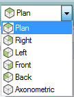
The model can be visualised in a number of ways by using the views dropdown on the main toolbar, as shown in Fig. 3. Switching to axonometric view will make it easy to see all surfaces of the room.
Fig. 3: The views dropdown on the main toolbar shows various possible views for the current model. The default is ‘plan’, but ‘axonometric’ is useful for visualising all surfaces of the model.
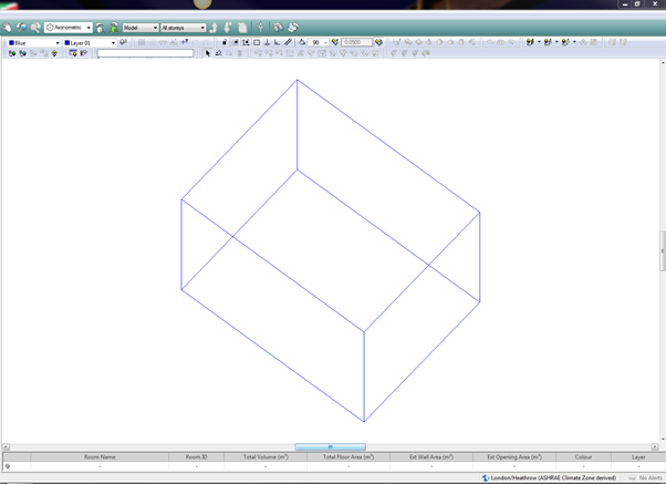
If you created a single room using the draw prism function, you should have a model that looks reminiscent of that shown in Fig. 4. The dimensions are important for the solar collector surface because the total surface area of the collector will dictate the flow rates needed by the fan in the solar collector system. For now, we will not worry about obtaining an exact size, but we can probe the surface area of an individual surface by clicking on it in the viewport or by selecting it in the list browser.
An important feature is the idea of “room-level” and “surface-level” selections. These can be considered as different viewing modes allowing selection of rooms or individual surfaces. To traverse between different selection levels, click the arrows on the main toolbar (shown in Fig. 5). Double-clicking on a room will also automatically traverse to the surface level. These levels will also be traversed when clicking on rooms or surfaces in the list browser.
Another important feature is the site rotation feature. This icon is the third one from the right on the main toolbar (see Fig. 5). The default site rotation is set to North, but the entire model can be pointed in a different direction using this icon. This will be important since solar collector surfaces are typically installed on South-facing walls.
Once the room is created, click the “save project” icon on the main toolbar. You may also be prompted to save the project if you open a different application using the applications tab. We will now import the TSC component into our session.
Fig. 4: A typical one-room model created using the draw prism function in ModelIT and displayed in axonometric view.
Fig. 5: Icons at the far right of the main toolbar. These functions are, from left to right: move up one level, move down one level, object list, site rotation, model viewer and refresh display.