Zone-level loads, sizing & related system setup
The zone-level autosizing process sets zone-level and airside control inputs in the context of basic system-level parameters. Depending upon the specific system type, these include the following parameters:
· zone-level heating and cooling load oversizing factors
· zone-level airflow for VAV boxes, fan-coil units, fan-powered boxes, active chilled beams, etc.
· outside-air ventilation rates as well as CO2 sensor control thresholds, where DCV is employed
· exhaust airflow and inter-zonal transfer airflows (typically as make-up air for exhausted air)
· reheat coil leaving air temperatures and flow rates
· radiator and chilled ceiling panel water flow rates (as of version 6.5)
· outside-air economizer damper minimum flow rates (incl. optional ASHRAE 62.1 calculations)
· outside-air economizer dry-bulb temperature high limits*
· energy recovery engagement, sensible and latent effectiveness, and device power*
· coil leaving air temperatures, temperature resets, and zone humidity control*
For prototype systems, the zone-level autosizing process provides means of engaging or disengaging system features, such as outside air economizers and airside energy recovery, from within the System Parameters dialog, in addition to manually changing these within the Loads Data spreadsheet for each system or within the ApacheHVAC airside network itself. The controllers in pre-defined systems also use pre-defined control profiles (which you may also use as you see fit). This allows system-operating schemes for unoccupied hours—e.g., temperature setback only, setback with fan cycling, or setback with fan cycling but no outside air—to be selected along with system schedules and setpoints. While these parameters and operating schemes can be manually changed, the dialogs provide basic inputs and automation for pre-defined systems.
While rooms or zones may be adequately conditioned with just the first stage of sizing completed, energy consumption for grossly over or undersized equipment will be far from what is should be. This will be particularly true in the case of performance for grossly oversized hot-water boilers and air-cooled or water-cooled chillers using pre-defined bi-quadratic performance curves. System-level loads calculation and sizing, which applies to coils, fans, water loops, chillers, DX cooling, boilers, heat pumps, etc., must be completed in order to appropriately scale equipment capacities and performance curves and thus to obtain performance and energy consumption results that reflect real-world applications.
The System Schedules and Setpoints dialog (see additional description below) sets room heating and cooling set points, operating schedules, including start-up and after-hours operation, and the control scheme to be used during unoccupied hours. It does so via automated editing of a pre-defined set of profiles that are referenced within the prototype systems and also applied to Space Data in the Apache Thermal view. The application of heating and cooling set points from the System Schedules dialog to Space Data for each conditioned space provides the fundamental basis for autosizing.
The System Parameters dialog (see additional description below) provides initial inputs for many of the zone- and system-level parameters in the list above, such as zone load oversizing factors and both air-handler and zone coil leaving air temperatures, as inputs to the autosizing of zone-level airflows, etc. It should be noted that oversizing factors are separately set with coils, water loops, and other heating and cooling equipment that is autosized only in the system-level stage of the process.
The ASHRAE 90.1 Performance Rating Method (PRM) Navigator within the VE provides additional interface dialogs and tools for ASHRAE 62.1 ventilation rates, exhaust airflow settings, and application of PRM Baseline fan curve inputs. The PRM Navigator interface is described in a separate user guide. The ApacheHVAC path to these parameters is described below.
The System Prototypes & Sizing navigator is an optional path for autosizing that is functionally equivalent to the set of five toolbar buttons within the ApacheHVAC view ( Figure 5-1: Systems setup and sizing toolbar in ApacheHVAC. ). Using this workflow navigator, which includes some minor additional features, requires that the target ApacheHVAC system file is named “proposed.asp”. This file name must be in place prior to using either System Parameters or Room Load Calculations. If not, the parameter changes and/or sizing process will not populate the Loads Data spreadsheet according to the rooms or zones assigned to the correct target system. When using this workflow navigator, the “proposed.asp” target system name must also remain in place (or be reinstated) for the Assign system parameters and room sizing data action within the navigator. The ApacheHVAC file name can be subsequently changed without consequence.
The naming convention described above is not be required when using the five-button toolbar within ApacheHVAC for System Schedules and Setpoints, System Parameters, Room and Zone Sizing, System and Plant Equipment Sizing, and System Sizing Reports, as described below.
Model set up for zone-level system autosizing steps
Unless the model has exceptionally small number of thermal zones, conditioned spaces and related thermal zones in model should first be grouped according to system or air-handler assignment using an appropriate Room Grouping Scheme.
Loading HVAC systems from library or project folders
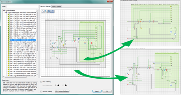 Figure 5-2: Open ApacheHVAC, load selected systems from the HVAC Prototype Systems Library as needed, and save the file.
 Additional systems can be loaded at any time and additional sizing runs performed as needed. Prototype systems can be modified or used as resources from which to copy elements for customizing or extending the capabilities of a particular system. For all but advanced users, however, it is recommended that initial system sizing and brief test simulations are completed prior to modifying the system configuration, components, or controls (substantial experience with ApacheHVAC is also recommended).
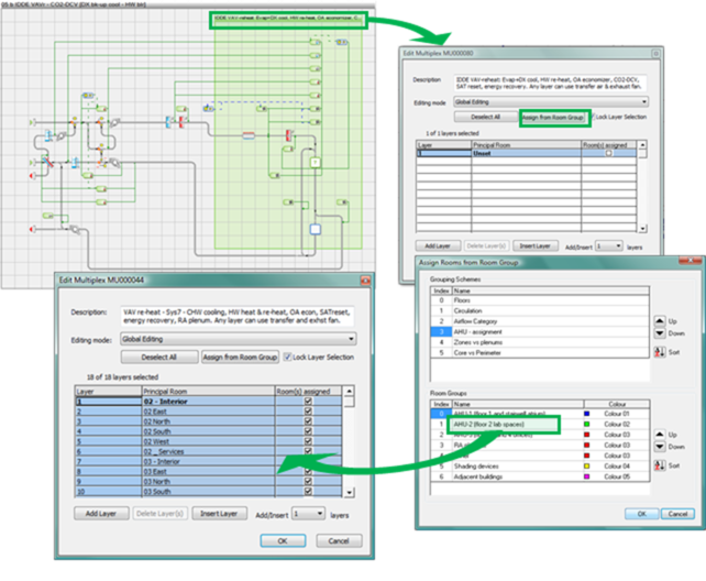
Figure 5-3: Use Edit Multiplex to assign user-defined groups of rooms or zones to each prototype system.
TIP: If you hold down the Ctrl key and clicking on the Room Group Index Numbers, you can select more than one Room Group for simultaneous assignment to a single HVAC network.
Once the rooms or zones have been assigned to all HVAC system networks in the current HVAC system file, proceed to using the following five buttons of the System Sizing toolbar in ApacheHVAC to set up and autosize the systems.
System Sizing toolbar
From left to right, the System sizing toolbar buttons provide the following functions:
· System schedules and setpoints
· System parameters
· Zones tabular edit view
· Global system parameter assign
· Room and zone-level sizing
· System equipment and plant sizing
· System loads, sizing, and ventilation reports
System Schedules and Setpoints
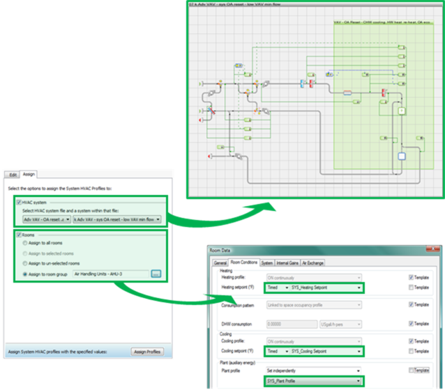
Figure 5-4: The System Schedules and Setpoints dialog has two tabs: the first tab is for editing and creating sets of coordinated HVAC profiles used in system controllers and Space Data; the second is for Assigning these profiles to specific HVAC networks and groups of room or zones served by that system.
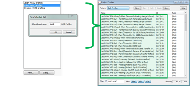
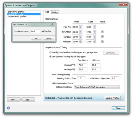
Figure 5 - 5 : The list window at the left of the System Schedules and Setpoints dialog is the means of selecting an existing HVAC profile set to be edited, assigned, or copied. Additional sets of profiles should be set up when the project includes an HVAC system and zones served by that system that will be operated with setpoints, schedules, or setback strategies that differ from that of other systems in the same project. A New HVAC profile set will start with default values, whereas a Copy will start with the values of the currently selected set. In either case, you will be prompted to add a prefix the schedule set name (up to four characters) that will be applied to all daily and weekly HVAC and SYS profiles in the automatically generated set.
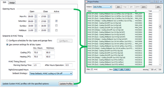
Figure 5-6: The Edit tab in the System Schedules and Setpoints dialog provides coordinated editing of the selected set of HVAC… and SYS… profiles used in HVAC system controllers and Space Data.
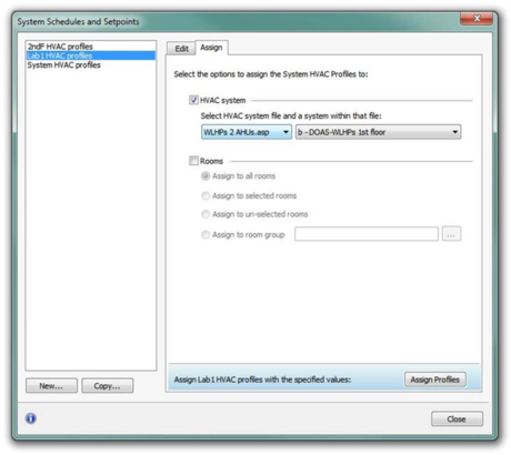
Figure 5-7: The Assign tab in the System Schedules dialog provides options for assigning a coordinated set of profiles to the components and controllers of a selected HVAC system and to Space Data. The standard set of “System HVAC profiles” is already assigned, by default, to all pre-defined prototype HVAC networks in the systems library. Therefore, profiles need be assigned to systems only when setting up an additional or alternate set of HVAC profiles. For rooms or zones in the model, however, the SYS profiles must be assigned to Space Data at least once prior to autosizing any ApacheHVAC networks for the project.
For a project wherein all zones use the same schedules and setpoints, simply leave the standard set of “System HVAC profiles” is assigned to all pre-defined prototype HVAC networks (as they are by default); edit and update as desired via the Edit tab of the dialog, and then go to the Assign tab (at least once) and select Assign to all rooms prior to clicking Assign Profiles.
NOTE regarding 24-hour operation: If 24-hour operation is to be used for all day types, simply select the Setback strategy called “None (24-hr. conditioned to Oc. Setpoints).” To specify 24-hour “opening times” with respect to HVAC operation for some but not all day types, set both the Open time and Close time for the desired day types to 0:00—for this to work correctly, however, After Hours Operation must be set to zero (0.0).
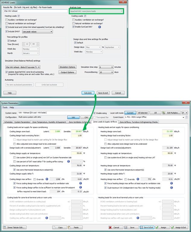
Figure 5-8: The Room/Zone Load Calculations toolbar button (or the equivalent step in the System Prototypes & Sizing navigator) runs ASHRAE Loads and populates the System Parameters interface for each network with loads results. Other relevant data, such as room volumes, is populated when rooms or zones are assigned to multiplex layers. The loads data and other settings in the System Parameters dialog for zone-specific airflow configurations and calculation of ASHRAE 62.1 ventilation rates feed into the calculation of zone airflows and related parameters.
Figure 5-9: The System Parameters dialog provides access to viewing and editing numerous parameters for system configuration, sizing, and control options. Edited parameters are applied to system components and controllers through ‘system parameter links’ upon clicking ‘Assign’. The ApacheHVAC User Guide part D - System Parameters Interface for HVAC Networks describes this in greater detail.
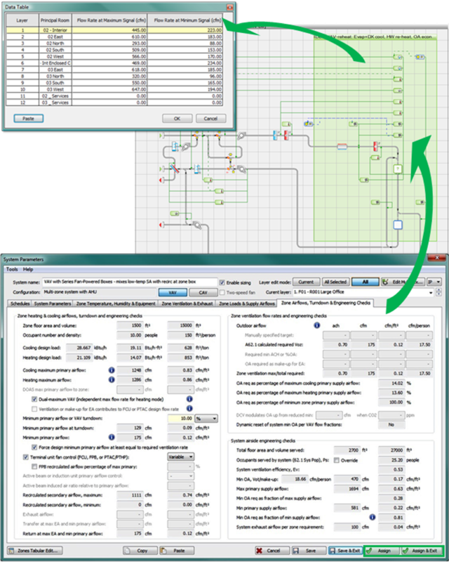
The Assign button in the System Parameters dialog assigns values to system components and controllers. This is also done automatically upon completion of zone-level autosizing when the ‘Update ApacheHVAC zone-level autosizing’ box is checked in ASHRAE Loads. Viewing the zone cooling and heating airflow rates for all multiplex layers confirms that this stage of autosizing has been satisfactorily completed.