Copies an image of the current view to the clipboard.
Graphics Toolbar
Open Display Settings
Opens the display settings window.
Click here for more information on the settings available.
Toggle Ground Plane
Turns the display of the ground plane on and off.
Ground plane is on by default.
Toggle Grid Lines
Turns the display of the grid lines on and off.
The grid is displayed in metric, minor lines representing 10cm, major lines representing 1m.
Grid lines are off by default.
Toggle Display Options
Clicking the button brings up various display options which can be toggled.
These include turning the display of: components, room names, model edges, component edges, and edge effects * on or off.
X-Ray View Mode
View the model in X-Ray Mode.
This shows the model as semi-transparent white on a black background.
Hidden Line View Mode
View the model in Hidden Line Mode.
This shows the model in an edges only mode.
There are two modes: removal - which eliminates hidden edges, and obscured - which shows hidden edges greyed out. In both modes windows can be made opaque if desired.
Removal mode and transparent windows are default.
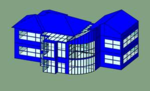
Shaded View Mode
View the model in Shaded Mode.
This shows the model in a simple flat colour mode.
The colours are determined by the currently selected ‘View > Colour > By …’ option in the VE.
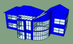
Textured View Mode
View the model in Textured Mode.
This shows the model with textures applied.
The textures are determined by the user (via the Assign Textures button in ModelIT) or by the surface type defaults.
Bump Mapping & Specular Mapping can also be enabled. * VE2015FP2
Component View Mode
View the model in Component Mode.
This shows the model as wireframe and all components as shaded.
Note: Only available if components have been placed in the model.
Allows the user to rotate the camera around the model.
Flythrough Camera
Enters Flythrough Camera mode.
Allows the user to freely navigate through the scene.
Walkthrough Camera
Enters Walkthrough Camera mode.
Allows the user to freely navigate through the scene at the current height.
Camera Position
Clicking the button will reset the camera to its initial position for the current mode. While in Arcball mode, the user can set the camera’s current position using various pre-sets from the dropdown menu. Orthographic View can also be turn on/off from the dropdown menu to provide a more ModelIT-esque view.
Orthographic View off
(i.e. Perspective View)
Orthographic View on
From North
View the model from the North.
From East
View the model from the East.
From South
View the model from the South.
From West
View the model from the West.
From Above
View the model from above.
Goto Room
Feature not currently available.
Clicking on the button will move the camera to the room currently selected in the VE.
Sky / Background Toolbar
Toggle Skybox
Turns the display of the skybox on and off.
When enabled the specified sky (from the dropdown) will be displayed in the background. When disabled the specified background colour will be display.
Skybox is on by default.
Background Colour
Allows the user to specify the background colour used when the skybox is disabled.
White by default.
Solar Toolbar
Toggle Shadows
Turns the real-time shadow display on and off.
In this mode the model will be shown with shadows applied. Component shadows can also be toggled on and off independently via the dropdown menu.
The sun’s position (and so the shadows) can be modified using the date and time controls. The shadows can also be animated using various options. See below.
Animate Shadows
Turns the animation of shadows/solar arc on and off.
There are various animations which can be used via the dropdown menu.
These include:
Time (daylight hours) - animates through the hours the sun is up for the specified day.
Time (24 hours) - animates through all hours for the specified day.
Days - animates through all days in the specified month at the specified time.
Months - animates through all months in the year using the specified day and time.
Days of Year - animates through all days in the year at the time specified.
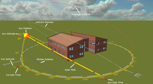
Toggle Solar Arc
Turns the display of the Solar Arc on and off.
The solar arc displays several pieces of information, including: site orientation (by the use of the compass), sun position (azimuth, altitude, and time), solar path (the arc) and sun rise/set times. The summer/winter solstices and autumn equinox can also be displayed via the dropdown menu. The size of the arc and sun can also be altered via the dropdown menu.
The solar arc can also be animated. See above.
Date & Time Selection
The date and time controls allow the user to modify the sun position for shadow and solar arc display. The date/time can be modified using the popup calendar, sliders and spin boxes.
Simulex Toolbar
Simulex
Clicking the icon brings up 3 options:
Open Project - allows the user to load a Simulex Project file (.spj) into the viewer.
Load Simulation - allows the user to open a Simulex Results file (.slx) into the viewer.
Close Project - closes the currently opened project (and simulation file).
Playback
Controls
Allows the user to Play, Pause and Stop simulation playback.
While playing, you can also fast-forward / rewind the playback at various speeds, i.e. x1, x2, x5, x10, x20.
You can also seek to a specific position using the slider.
Floor Split
Controls
When in ‘Floors’ display mode the user can separate the floors in various ways using the controls above.
The user can adjust the vertical (Z plane) and horizontal (XY plane) separation of the floors using the first two sets of arrows respectively.
The positions can also be reset using the last button.
When the floors are fully expanded in any horizontal direction, they can then be flattened to lie on the same vertical plane providing a Plan view of the floors.
The Plan view can also be quickly accessed by pressing the reset button when the floors are in their initial positions.
Display Mode
Allows the user to select 3 different display modes:
Model - shows your VE model without any Simulex geometry overlaid.
Floors + Wire - shows your VE model in wireframe mode with the Simulex geometry overlaid.
Floors - hides your VE model and displays just the Simulex geometry.
Transparency Options
When displaying the Simulex geometry you can toggle the transparency of the floors and walls.