Techniques for Modelling Flow in Façades and Flues
The theory applied in MacroFlo is based on the flow characteristics of openings that are small in relation to the spaces they connect. Whilst this is a good approximation for most windows, doors and louvres, it is a poor approximation in some other modelling situations, notably flow in façade cavities and flues. For this type of situation, where the openings have a diameter similar or equal to the diameter of the adjacent spaces, adjustments to the opening parameters are necessary in order to achieve a good model.
In the case of flow in a façade cavity, there are three sources of flow resistance:
1. Resistance associated with the exchange of air between the cavity, the outside environment and the adjacent building spaces.
2. Resistance offered by obstructions in the cavity. These may take the form of constrictions, obstructions protruding from the sides, walkways etc.
3. Frictional resistance with the walls of the cavity.
These will now be dealt with in turn.
External Openings
On the whole, openings in this category are well represented by the standard theory and require no adjustment.
Constrictions in the Cavity
There is an extensive data available on the resistance to flow in ducts imposed by constrictions, expansions, contractions, grilles and other forms of obstruction. This data can be applied in MacroFlo in the following way.
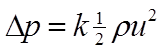
A flow coefficient, k, is defined for the obstruction, as follows:
(14)
where

is the pressure difference across the obstruction

is the flow coefficient (sometimes referred to simply as ‘resistance’)

is the air density

is the mean air speed at a specified cross section of the flow
The point at which u is defined needs to be specified carefully. If u is defined for all obstructions at a common point in the flow (for example an unimpeded section of the duct), it is possible to combine k coefficients for a set of obstructions in series by simple addition.
If k is known for an obstruction or a set of obstructions it can be used to calculate a correction to the area of MacroFlo opening such that the opening will have the desired flow resistance.
Let us assume that k is defined in terms of the mean speed of air in the unimpeded duct, which has area A d , and that the obstruction is to be represented by a MacroFlo opening of area A o .
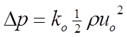
The pressure/flow relationship for the MacroFlo opening is
(15)
where
is the pressure difference across the opening

= (1/0.62)
2 is the flow coefficient (sometimes referred to simply as
‘resistance’) for openings which are small compared to their adjacent spaces

is the mean air speed of the air flow through the opening
u o is linked to u by the flow conservation equation
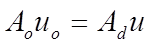
(16)
from which, by equations 14 and 15,
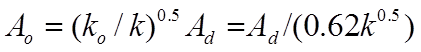
(17)
If the value of A o calculated from equation 17 is used in MacroFlo the opening will correctly represent the resistance of the obstruction.
The most common type of obstruction is an orifice plate or grille, which abruptly reduces the area available to the flow by a factor σ, where σ < 1. For this type of obstruction a good approximation to the flow coefficient (applied to u in the unimpeded duct) is
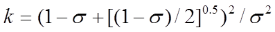
(18)
Wall Resistance
The resistance of a duct due to friction with its walls can be expressed in terms of a friction factor, f:
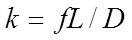
(19)
where
is the flow coefficient, as defined in the previous section

is the friction factor

is the length of the duct

is the hydraulic diameter of the duct
For a duct with one dimension much larger than the other, D is twice the width, w, so
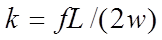
(20)
The friction factor, f, depends on the speed of the flow (usually expressed in terms of Reynolds number) and the roughness of the duct’s sides. Values can be read off a Moody diagram.
For typical flow speeds in façade cavities (i.e. Reynolds numbers greater than about 50000 and roughness factors ε/D greater than about 0.01), a good approximation to f is given by
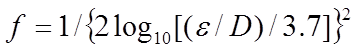
(21)
where

is the surface roughness factor, defined as the ratio of the typical heights of
surface features to the hydraulic diameter.
Combining equations 20 and 21 we obtain
(22)
In reality this frictional resistance is distributed evenly along the duct. In MacroFlo it must be aggregated into discrete openings. Floor slabs are convenient places to position such openings.
The value of k calculated from equation 22 may be substituted directly into equation 17, or may alternatively be combined with a flow coefficient representing the resistance of an obstruction at the floor slab level:
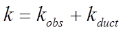
(23)
where

is the obstruction flow coefficient from equation 7 or similar

is the duct resistance flow coefficient from equation 11,
is the combined flow coefficient.
Example
A façade cavity has a width of 0.5m and a cross-sectional area of 10m 2 . Floor slabs are spaced at 4m intervals up the cavity. At each floor level the cavity is crossed by walkways that reduce the area available to the flow by 30%. For the calculation of frictional resistance it is assumed that there are irregularities on the sides of the cavity of typical dimension 0.05m. We need to calculate the area of a MacroFlo opening at each floor level that will correctly reproduce the resistance of the walkway and the frictional resistance of one storey of the cavity.
From equation 18, setting σ = 0.7, we find
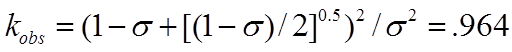
(24)
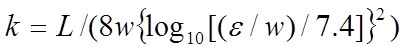
From equation 20, with L = 4, w = 0.5, ε = 0.05,

(25)
and therefore by equation 23,
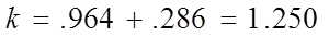
(26)
Finally, using equation 17 with A d = 10, the MacroFlo opening area is calculated as
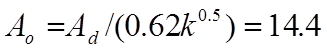
(27)
