Steps in performing a VE Compliance analysis
The following workflow is recommended for preparing and performing a compliance or EPC analysis for Part L2 (2013-2014). The plan need not be followed slavishly. Variations can be made in the ordering of the tasks and experienced users may wish to take alternative approaches to some of the stages. The purpose of the plan is to guide you through the basic process.
The workflows for compliance testing and EPC generation follow a similar paths, differing only in the final stages.
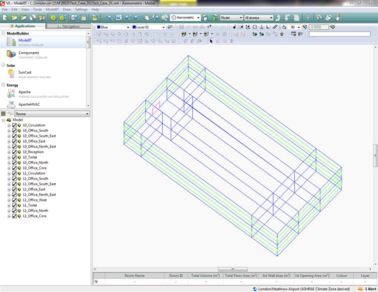
Step 1. Create geometry
The process begins with the entry of building geometry in ModelIT.
Step 2. Set location and weather data
The building location is specified in the APLocate utility. The L2 regulations currently cover locations in England and Wales.
Weather data for simulation-based Part L2 (2013-2014) assessments is provided by CIBSE – a Test Reference Year (TRY).
TRY’s and DSY files are provided for 14 UK locations;
· Belfast
· Birmingham
· Cardiff
· Edinburgh
· Glasgow
· Leeds
· London
· Manchester
· Newcastle
· Norwich
· Nottingham
· Plymouth
· Southampton
· Swindon
You will need the TRY corresponding to the nearest of these locations to the building location. A licence to use this data must be obtained from CIBSE. IES acts as an agent for CIBSE and the licence to use the data may be purchased online via the
IES website. If you use this option, copies of the files in the IES .fwt format will be provided with installation instructions.
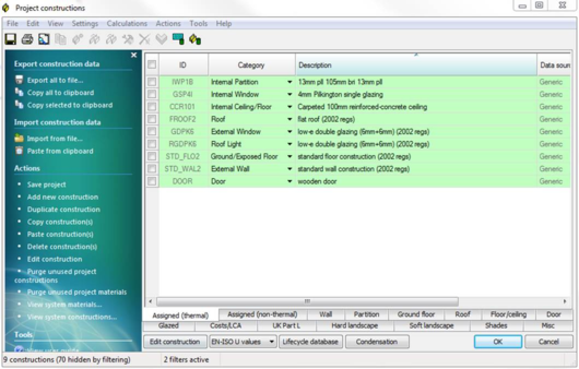
Step 3. Create and assign constructions
Constructions for building elements such as walls, roofs and glazing are created in the Constructions Database (CDB) utility accessible via Apache View or VE Compliance. They should satisfy the U value requirements of Criterion 2. The construction definition should include allowance for non-repeating thermal bridging, using an area-based thermal bridging coefficient. Constructions may be assigned to building elements in either Apache View or VE Compliance.
Step 4. Set building type and general data
At this stage you may wish to go to VE Compliance and set up some of the high-level data required for the compliance analysis.
First, check that the Regulatory framework (‘Regs’) selector is set to ‘Part L2 (2013) – England’; or Part L2 (2014) –Wales’
In the ‘Building settings’ box near the bottom of the screen select a building type from the list. This indicates the type of building for ratings purposes and determines what room function/activity can be specified in the building and applied to individual rooms. The glazing area is determined by the activity and whether it is side-lit, top-lit or unlit.
For a building with multiple use, the various parts can be analysed by including NCM activities from other NCM building types in the room-level assignments. This can be done for individual rooms, groups of rooms (using Edit Group Attributes) or via Tabular Room editing.
Not all zones may need to be included in a compliance run for example separate buildings may exist within the same model. The part(s) of the building included in a particular analysis is defined by the settings of the check boxes ‘Include room in Building Regs analysis?’ for each room on the Space Data Building Regulations tab.
Step 5. Create HVAC and DHW Systems
It is recommended that HVAC and DHW systems characteristics for VE Compliance analysis are specified within the framework of Apache Systems. Apache Systems provide a robust and uncomplicated system model that has been harmonised with that provided in iSBEM with the aim of providing a point of reference and common ground between these alternative compliance methods.
Systems are one of the aspects of building design where substantial carbon emissions improvements can be introduced. The system data is therefore under your control, and it is shared between the real building (as displayed in the Apache module) and the actual building (as displayed in VE Compliance).
The Apache System dialogs as they appear for simulation-based ratings methods are described in detail in the VE Compliance user guide. The following is a summary.
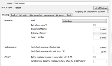
The Apache System HVAC model has three key parameters, which can be defined in summary as follows:
SCoP – the efficiency of the heating system
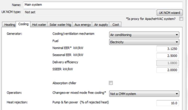
SSEER – the efficiency of the cooling system (if present)
Auxiliary Energy Value – energy required for fans, pumps and controls
These are the most important parameters featuring in the calculation of the energy consumed by the space heating and cooling systems. Taken together with the fuels specified for heating and cooling, they encapsulate most of the important data about system performance in relation to carbon emissions.
On the Apache System dialog there are other parameters that are linked with the heating and cooling system efficiencies and do not represent independently editable settings. For example, the heating system’s Generator seasonal efficiency and Heating delivery efficiency are linked to the SCoP by the relation
SCoP = (Generator seasonal efficiency) × (Heating delivery efficiency)
so that in terms of carbon emissions they can be viewed as secondary to the SCoP.
On the cooling side an analogous relationship exists between SSEER and the following parameters:
EER – the cooling system generator energy efficiency ratio or COP
CDE – the cooling delivery efficiency, and
HRP – the heat rejection pump and fan power fraction
namely
SSEER = EER * CDE / (1 + (EER + 1)*HRP)
In terms of carbon emissions EER, CDE and HRP can thus be viewed as secondary to the SSEER.
These ‘secondary’ parameters are important for certain design tasks in the Apache module – for example the calculation of boiler and chiller loads. But for VE Compliance, SCoP and SSEER are the key efficiency measures.
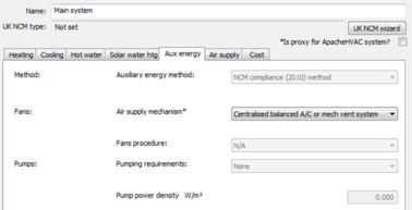
Auxiliary energy value is a concept that has been developed in connection with the NCM methodology. This parameter indicates the power consumption of fans, pumps and controls associated with the space heating and cooling systems. It is expressed in terms of Watts per square metre of floor area served, and is incurred when the heating, cooling or ventilation systems are running.
Auxiliary energy values are derived by the UK NCM System Data Wizard in line with guidance in the NCM Modelling Guides for both England (2013 edition) and Wales (2014 edition).
The UK NCM System Data Wizard has been developed as a replica of the analogous facility in iSBEM. Its purpose is to guide you through the process of describing the system properties and to generate values for the three key parameters.
In addition to the key parameters mentioned so far, there are other system parameters of importance such as heating and cooling system fuels, ventilation heat recovery effectiveness. These are also generated automatically from data entered in the wizard.
Other data entered via the wizard, such as metering provision, also affects system performance without being reflected in parameters appearing on the main Apache System dialog. More information on using the wizard is provided in the VE Compliance User Guide.
Nomenclature for heating, cooling efficiencies has recently been introduced that aligns VE Compliance with the NCM. Definitions of these can be found in the DCLG document ‘Non-Domestic Heating, Cooling and Ventilation Compliance Guide’. This is freely downloadable from the DCLG website:
SCoP and SEER values for commonly available plant can be found at:
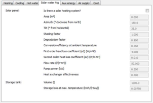
The Apache System approach to DHW systems is slightly different from that adopted in iSBEM, but allows essentially the same flexibility. By default DHW is assumed to be the supplied by the same Apache System as the space heating system. If the building has a separate DHW system this can be created as an Apache System and connected to the rooms it supplies by means of the DHW System selector on the Space Data System tab. The efficiency of the DHW system must be expressed in terms of a generator (eg boiler) efficiency and a DHW delivery efficiency, the overall efficiency of the system being the product of these two efficiencies.
The DHW system wizard enables the definition of the delivery efficiency, storage and the secondary circulation efficiencies and pumping power. The DHW heating demand can be derived from a solar water heating system. This system will use solar power, when available, to pre-heat the water for the DHW system. A storage system can be defined for the solar water heating system.
The assignment of HVAC and DHW systems to rooms is described in Step 8.
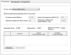
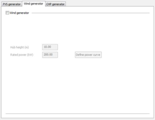
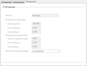
Step 6. Define renewable systems
Four renewable system types are available for use within the ApacheSim actual building:
· Photovoltaic systems (PVS)
· Wind
· CHP
· Solar water heating
The first three are defined on the Renewables dialog (Earth symbol on toolbar) and the last is defined per DHW system on Apache Systems dialog.
CHP should be sized to provide the base load of heating for the building and the power generated will be used to offset the electrical energy usage in the building.
Wind and Photovoltaics will, when the prevailing weather conditions permit, provide electrical energy that will offset electrical energy usage in the building.
Note: Solar water heating is not classified as a renewable in the SBEM outputs.
Note: the parameters and models of renewables are different between SBEM and ApacheSim. In most cases the ApacheSim model is more sophisticated.
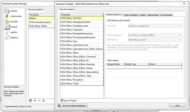
Step 7. Create or import room templates
An efficient way to assign Space Data is by means of Thermal templates. A Thermal template contains a collection of settings that define the internal conditions applying in a room of a given kind. By defining these conditions centrally you can assign them quickly to large numbers of rooms and transfer them readily to other models via the Import Template mechanism.
Room Templates contain data arranged on tabs under the headings Building Regulations, Room Conditions, Systems, Internal Gains and Air Exchanges. Not all this data is used in VE Compliance assessments, some being overridden by standard settings. It is therefore important to understand where and how the various components of Room Template data are used. In particular, if you do not intend to use the analysis options available in the Apache module (which analyses the real building) you do not need to set Room Template data on the Room Conditions and Internal Gains tabs, or create air exchanges of the Auxiliary Ventilation type.
One of the attributes that can usefully be set in the Room Template is the NCM Activity, which is always partnered with an NCM Building Type. If these attributes are set in the Room Template, rooms assigned the template will automatically have the NCM Activity (and all the Space Data associated with it) set in VE Compliance.
If you adopt a policy of including NCM Activity settings in your Room Templates you will save a lot of time and effort assigning NCM Activities to individual rooms and groups of rooms in VE Compliance.
The next section provides guidance on the Room Template settings.
Step 8. Edit Space Data
When creating Room Templates it is important to understand which Room Template settings will be used in VE Compliance, which are overridden by standard activity-based settings, and which are editable.
The content of the Space Data tabs and their function in Part L (2013-2014) is summarised below. A fuller account is given in the section 5, Space Data.
General tab
The General tab displays general data about the room, including its name, ID, floor area measures and templates.
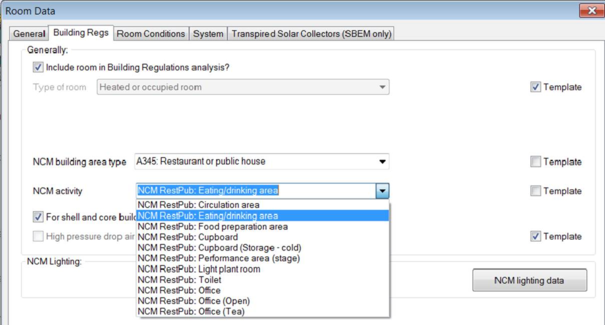
The NCM Template is unique to VE Compliance, and is used to import the NCM activity data applicable to the room. Each heated or occupied room (defined using the ‘Type of room’ setting on the ‘Building Regs’ tab) must be assigned an NCM activity. This defines the standard operation pattern of the room for the purpose of L2 (2013-2014), which is defined by attributes on the various Space Data tabs. The assignment of these Space Data attributes is effected by the NCM template corresponding to the activity.
Each NCM building type has a predefined list of NCM activities available to its rooms.
As noted above, it is recommended that the NCM activity is set as an attribute of the Room Template. This saves work as it means that the activity will be automatically set for all rooms assigned that template. An NCM activity is only meaningful in the context of a building type, so this, too, must be set in the template.
If the NCM activity is set in the template it may (like other template settings) be overridden in the room by un-ticking the Template check box and selecting an alternative activity from the drop-down list.
For unheated rooms (those with Type of room set to anything other than Heated room), the NCM activity is undefined and is not displayed. In this case a special NCM template called ‘NCM unheated space’ is automatically assigned to the room.
Building Regs tab (data taken from Room Template but editable)
This tab is displayed only in VE Compliance. Some of the fields can be set in the Room Template. Others appear only in the VE Compliance and can be set on a room-by-room basis, using Edit Group Attributes or via Tabular Space Data.
Include room in Building Regs analysis? is a check box which is shown when a room is queried or selected whilst in VE Compliance allows you to restrict the Part L analysis to part of the building only.
The Type of room attribute is normally set to ‘Heated or occupied room’, but the following alternative settings are provided to cover various types of unheated space:
· Unheated roof – use this type for an unheated roof space lying outside the insulated building envelope (i.e. where the insulation is at ceiling level).
· Glazing cavity (required only rarely) – use this type for a glazing cavity that has been modelled as a separate room for simulation purposes.
· Unheated buffer space – use this type for other types of unheated space attached to the building but lying outside the insulated building envelope. Examples are car parks and lean-to outbuildings.
· Internal void or warm roof – use this type for floor and ceiling voids, and for roof spaces that lie inside the insulated building envelope (ie with insulation at rafter level).
In the case of the first three types listed above – all representing types of unheated buffer space – an external ventilation rate must also be entered for the purpose of calculating U values for Criterion 2. All the above types of room are excluded from the floor area summation upon which the emission ratings are based.
NCM lighting data pops the NCM lighting data dialog, which is described in section 5. This defines the characteristics of lighting control systems which are to be modelled using the NCM simple lighting control method. Lighting gains which are subject to this type of control must be identified on the Internal Gains tab.
The Building Regs tab also displays check boxes relating to shell and core buildings and high pressure drop air treatment, and the results of the Criterion 3 assessment for the room, as detailed in section 5.
The settings NCM Building type and NCM Activity together specify the activity assigned to the room for the compliance analysis, which in turn (via the NCM Template) sets the standard conditions applied for occupancy and plant operation. While these attributes are optional in the Room Template, it is a good idea to set them there to save effort in VE Compliance.
Room conditions tab (data taken entirely from NCM template)
The data set on this tab in the Room Template will be ignored in VE Compliance (but it will be used for assessments of the real building in the Apache View).
In VE Compliance, the data on this tab can be viewed but not edited. It is taken from the NCM Template as part of the specification of standard occupancy and plant operation conditions.
System (taken from Room Template, but editable)
The data set on this tab in the Room Template will be used in both VE Compliance and in the Apache module.
In either of these views, data on this tab is initially taken entirely from the Room Template (but as usual you have the option to override this data in individual rooms) or via Tabular Space Data (as applicable).
For compliance assessments, the important parameters on the System tab are the following.
In the Systems box:
· HVAC system – this indicates the Apache System serving the room’s space conditioning needs
· DHW system – this indicates the Apache System serving the room’s hot water needs including any solar energy system. An individual DHW system is recommended.
In the System outside air supply box:
· Free cooling flow capacity – this indicates the maximum intake of outside air that is available for free cooling. In the case of a naturally ventilated room, a value of 5 ach would be typical to model ventilation by window opening. In the case of an air conditioned room, where the outside air is brought in via the system, it would be usual to express the value in l/(s·m2) and a value of 0.5 in l/(s·m2) would be typical. Note that this figure represents the additional outside air intake over and above the minimum ventilation level. Free cooling is covered further in the User Guide.
Parameters on the System tab that can be ignored are:
· Auxiliary ventilation system – this is not applicable because under the NCM conventions there is no conditioning of ventilation air.
· Sizeable parameters (shown in blue) – sizing plays no part in VE Compliance.
· Humidity limits – these are disabled for VE Compliance assessments in line with the conventions applying in the NCM systems approach.
· Flow rate and profile for System outside air supply – in VE Compliance this type of air supply is replaced by standard ventilation patterns handled by Auxiliary Ventilation air exchanges.
The setting of data on the System tab is closely linked with the setting of data in Apache Systems, which is dealt with below.
Internal gains (taken from NCM Template – lighting editing permitted)
In the VE Compliance Space Data, this data is taken from the NCM Template as part of the specification of standard occupancy and plant operation conditions. It can be viewed but, with the exception of the lighting data, should not normally be edited.
An exception to this rule can occasionally be appropriate where rooms have been subdivided with horizontal partitions for modelling purposes. In such cases it is permissible to distribute the gains as appropriate among the sub-spaces. However, it is your responsibility to ensure that the total gains for the room are as specified in the NCM template.
The lighting data in VE Compliance has a special status. Whilst it is initially set from the NCM Template (activity) it may be edited in order to model improvements to lighting system efficiency over that assumed in the notional building. The types of edit permitted are a) changes to the gains and associated power consumptions of the lights and b) changes to the profiles applied to the lighting.
The lighting levels laid down for the different NCM room activities are specified in terms of a lighting illuminance (lux). The rules for the notional building translate this to a power consumption (and corresponding room gain) expressed in W/m2 using an installed power density factor (W/m2 per 100 lux). The power density factor set in the NCM database is 3.75 W/m2 per 100 lux for offices and similar rooms such as classrooms, seminar rooms and conference rooms, and 5.20 W/m2 per 100 lux for rooms of other types. In an office, for example, an illuminance level of 500 lux lighting level would require a power input of 18.75 W/m2.
However, the lighting data is not fixed at the NCM template values, and there are a range of ways of specifying reductions to lighting power consumption in the actual building, achieved either by efficient lighting systems or by lighting controls. These options are described in Section 5.6.
It is important to emphasize that where changes are made to the lighting data, this must be done in the rooms, not in the NCM Template (which is uneditable). Data for a group of rooms may be edited together by means of the ‘Edit group attributes’ toolbar icon or via the Tabular Room Edit facility.
Air exchange (auxiliary vent from NCM Template, other vent from Room Template)
Some of the data on the Room Template’s Air Exchange tab is used in VE Compliance, and some is overridden. The rules are as follows.
The activity (NCM Template) for a room specifies a rate and a schedule for minimum ventilation supplied to the room. This ventilation appears in the NCM template as an air exchange of type Auxiliary Ventilation, which replaces any other Auxiliary Ventilation air exchanges that might be assigned to that room by means of the Room Template or manual additions. By contrast, other types of air exchange (those of type Infiltration or Natural Ventilation) assigned to the room by the template or otherwise are retained in VE Compliance.
One further rule is that any settings for ‘System outside air supply’ on the System tab are, like Auxiliary Ventilation air exchanges, ignored in VE Compliance.
Under normal circumstances auxiliary ventilation should not be edited, as this data forms part of the NCM activity specification. There is one exception to this rule: if ventilation is provided by an ApacheHVAC system (at the rate set in the NCM template), it would be necessary to turn off the auxiliary ventilation.
While the real (Apache View) and actual (VE Compliance) systems are in most respects identical, one difference is enforced in VE Compliance because of the way minimum ventilation is specified in NCM. For the real building there are controls on the Space Data System tab allowing you to specify air supplied to the room in the form of a ‘System air supply’. In VE Compliance all such air supplies are handled by Auxiliary Ventilation air exchanges, and for this reason the System air supply is disabled in this View. Following on from this the settings in Apache Systems dealing with setting the condition of the System air supply do not play a part in VE Compliance. In VE Compliance, ventilation is always supplied to rooms (or their terminal HVAC units) at outside air temperature, in accordance with principles laid down in the NCM methodology.
Infiltration in VE Compliance is derived from permeability and other parameters specified in the Building & System Data dialog.
More guidance on ventilation in compliance assessments is provided in Appendix A of this User Guide.
Step 9. Set Building & System Data
We now return to the Building & System Data dialog to prepare for the compliance or EPC simulations. If the ‘Set Building & System Data’ button is not visible at the bottom of the screen, move the cursor into an empty space on the model workspace graphic and click once.
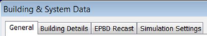
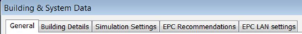
Under the ApacheSim framework Building & System Data is distributed over four tabs for Compliance and five for EPC.
Compliance:
EPC:
The Building & System dialog, which may be accessed either via the Building Settings menu ‘Set Building & System Data’ or via the Settings menu, allows you to enter general data relating to the building and its systems required by the BRUKL and EPC analyses and ratings calculators. It also allows the editing of Apache simulation settings for compliance simulations.
General
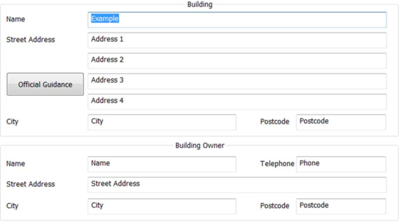
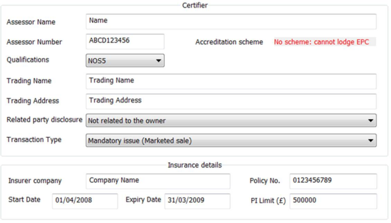
This tab takes different forms for compliance and EPC generation. The screenshot below is for EPC generation. For compliance the format is simpler, with the Building and Building Owner sections taking essentially the same form and the Certifier section following the form of the Building Owner section.
These entries provide data general for the BRUKL or EPC ratings calculator. Omitting self-explanatory entries the fields are as follows
Certifier Assessor number (EPC only): Unique EPC Assessor number, which will be stored in the computer’s registry after an EPC has been successfully generated.
Accreditation Scheme (EPC only): This is the scheme the assessor is accredited wit. Set automatically from Assessor Number.
Qualifications (EPC only): Qualification level of assessor. Must be Level 5 for DSM analysis.
Trading name & Address (EPC only): The employer or the trading name and address of the energy assessor.
Related Party Disclosure* (EPC only): Any related party disclosure by the Energy Assessor.
Transaction Type* (EPC only): The transaction type which has prompted the generation of the EPC.
*Related Party Disclosure and Transaction Type must be set before an EPC can be generated.
Building Details
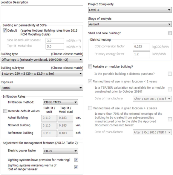
This tab allows for the input of data used in ratings analysis common to the two types of ratings analysis, and certain additional information required for compliance or EPC generation. The screenshot below is for EPC generation. For compliance the format is mainly identical but lacks the ‘EPC’ section and includes a question about LENI lighting analysis.
Note: When Wales is the active regulation mode, the dialog will contain an additional ‘Is mains gas supply available on site?’
Building air permeability at 50 Pa (m3/(m2.h))
Two values should be entered for building air permeability, for different categories of NCM activity: ‘Side-lit and unlit spaces’ and ‘Top-lit and metal-clad’ spaces. These space categories are subject to different permeabilities in the notional building, and may also optionally be treated differently in the actual building. The permabilities will be used to calculate infiltration rates for rooms in the actual building. The values must be no more than 10 m3/(m2 h).
Ticking the Default check box sets the values which apply in the notional building.
Infiltration method
Choose between alternative methods for the calculation of infiltration rates as a function of permeability: CIBSE Guide A and CIBSE TM23.
Building Type, Building sub-type, Exposure
These settings are inputs to the CIBSE Guide A method.
Choose the options that best describe the building. Infiltration rate settings will be updated accordingly.
Infiltration rates
Here are displayed the infiltration rates for the Actual and benchmark buildings calculated using the selected Infiltration method from the parameters above. The reference building applies a permeability of 10 m3/(m2 h).
Tick Override default values to enter alternative values (if supported by suitable justification). If the actual building values are edited using this facility the notional and reference building values will be adjusted in proportion.
Adjustment for management features
These settings allow credit to be taken in the BER calculation for management features applied to electrical power and lighting.
· Electric power factor
· Lighting systems have provision for metering?
· Lighting systems metering warns of ‘out-of-range’ values?
Project Complexity
Set the project complexity according to the official guidance.
Stage of analysis
Set whether the building is analysed ‘As designed’ or ‘As built’.
Shell and Core Building?
Tick this option to define building as a shell and core building (shell and core rooms as defined on Building regs tab of Space Data)
District Heating
This section is only active when a system with Heat source/fuel type set to District Heating is assigned to a room in the building.
District Heating CO2 Conversion Factor: Enter the CO2 Conversion Factor to be used by systems whose heat source/fuel type is District Heating.
Primary Energy factor: The conversion factor used to calculate the Primary Energy consumption associated with the District Heating system energy use.
Portable or Modular Building
Tick to define the building as Portable or Modular and set the related inputs Planned time of use in given location and further related input options.
Has LENI lighting calculation been carried out? (compliance only)
Specifies whether a calculation following the Lighting Energy Numerical Indicator (LENI) method has been carried out for the building as an alternative to complying with the lighting efficacy standards as specified in the Non-Domestic Building Services Compliance Guide.
Is mains gas supply available on site? (Wales 2014 only)
Tick if mains gas is available on site.
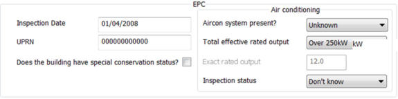
The following parameters apply to EPC analysis only
Inspection date
The date on which the energy assessor inspected the building for the purposes of energy calculations for the EPC.
Enter in the format dd/mm/yyyy
UPRN
The Unique Property Reference Number (UPRN) of the building (must be 12 digits).
Does the building have special conservation status?
Tick the box if the building has a special conservation status (i.e. the building has been identified as being: one of special architectural or historical interest, in a conservation area, in a designated area of special character or appearance, or of traditional construction).
Air Conditioning
Enter details of the air conditioning system in the building. Not used in calculations (HVAC data is defined in Apache systems/System Wizard) but instead used in EPC report.
Aircon system present?: Specify if air conditioning system is present in the building (if applicable).
Total effective rated output: If actual output is known then choose ‘EXACT’ and enter value in ‘exact rated output’ input else choose dropdown option that matches estimated value.
Inspection status: Indicate whether an air conditioning inspection been commissioned for compliance with Energy Performance of Buildings Regulations.
EPBD Recast (compliance only)
Use the inputs on this tab to confirm that consideration has been given to the use of ‘alternative energy systems’ as defined in the recast EPBD.
Simulation Settings
Use this dialog to edit the settings for L2 (2013-2014) ApacheSim compliance and EPC simulation. These settings are shared (as appropriate) by all simulations in VE compliance, but may be overridden for test runs. Simulation settings are described in the VE Compliance and Apache View user guides.
The special features applying for the various types of VE Compliance simulations are as follows. Results file names are given a prefix to distinguish the following types of simulation:
· Compliance simulation for actual building (including test run) - prefix ‘a_’
· Compliance simulation for notional building (including test run) - prefix ‘n_’
· EPC simulation for reference building (including test run) - prefix ‘r_’
For compliance simulations and compliance test runs the weather file is automatically set to the Test Reference Year (TRY) appropriate to the building location.
Options are provided, as in the Apache module, to incorporate
· SunCast link? – tick this box if you wish to use SunCast solar shading data in the simulation of the actual building.
· MacroFlo link?
· ApacheHVAC links?
· If these options are used, special care must be taken with ventilation settings and profiles to ensure that these are consistent with the standard room conditions laid down for L2 (2013) simulations. Guidance on this issue is provided in Appendix A. Where an ApacheHVAC system is used, the standard ventilation rates may be included in the system air supplies. See Appendix A for further guidance on ventilation settings.
· Radiance link? Tick this box if you with to use data from Radiance to inform lighting control/dimming in simulation
· The ‘Auxiliary ventilation air exchange?’ check box is ticked automatically. This is because auxiliary ventilation air exchanges form part of the standard room conditions for Part L2 (2013-2104) simulations.
· Natural ventilation air exchange? – tick this box if you have specified any ventilation by means of natural ventilation air exchanges
In the case of compliance simulations, ticking the check box Use existing results for notional building bypasses the simulation for the notional building in cases where this building has not changed since the previous compliance simulation. This would be the case if, for example, the only input to have been changed was a system efficiency.
The same applies for the option Use existing shading file.
In the case of compliance simulations, the simulation period is forced to the whole year, and Simulation Options are forced to standard settings to ensure uniformity.
Preconditioning period – make sure (using test runs if necessary) that this is sufficient to establish a realistic starting condition for the simulations.
You may also change the reporting interval and output options to generate more detailed results data for Vista.
Note that the weather file is forced to the appropriate TRY dataset for compliance simulations. If this file is not present compliance simulations will not be enabled.
EPC Recommendations (EPC only)
Use inputs on this tab to indicate recommendations to be passed to the EPC ratings analysis.
EPC LAN settings (EPC only)
Settings on this tab specify the use of a proxy server for the EPC assessor’s LAN.
Step 10. Inspect notional and/or reference building
Select ‘Notional’ or ‘Reference’ from the Current model selector at the top right of the screen. You can then inspect the notional or reference building. Note the changes to glazing (and in some cases doors), constructions, Apache Systems and Space Data. You may if you wish perform test simulations on the notional or reference building to check its performance over periods of a few days up to a year.
Under the NCM rules, the notional and reference buildings are generated automatically from the actual building and are uneditable.
Step 11. Perform test runs
Before committing to a full compliance analysis it is generally advisable to check the model settings by performing one or two test runs on the actual building. This is done using the button ‘CO2 emissions: test run (actual building)’. Test runs may also be performed on the notional building.
Simulate the building for a few days in winter and a few days in summer. View the results in Vista and check that the model is behaving as designed. In particular, check room temperature control, the operation of mechanical and free cooling and take a look at system loads and energy consumptions. This feedback provides a check on the overall design and helps eliminate model input errors.
Step 12. Perform compliance or EPC analysis
When you are satisfied that the actual building model is performing as intended, click on the button ‘CO2 Emissions: Part L compliance’ or ‘Generate EPC’. The software will immediately begin the analysis.
The first stage of the compliance analysis is a check on building element U values as required by Criterion 2. Any failures will result in a screen message and the analysis will halt.
The next step (for compliance or EPC analysis) is the simulation of the actual building. Progress is indicated on the screen.
This is followed by simulation of the notional or reference building.
In the case of compliance, results from the actual and notional buildings, together with data provided on the Building & System Data dialog, is then fed into the BRUKL compliance calculator. Results for Criterion 1 and Criterion 3 will be displayed on the Results tab (and, in the case of Criterion 3, for individual rooms on the Space Data Building Regs tab).
In the case of EPC analysis, results from the actual and reference buildings, together with data provided on the Building & System Data dialog, is fed into the EPCGen analysis calculator.
When the process is complete a summary of the result of the compliance or EPC analysis will be displayed on the Results tab, and you can click on a button to display the compliance document generated by BRUKL or EPCGen.
Step 13. Review, revise and repeat as necessary
If the result is satisfactory you may move on to the next stage. Otherwise you will need to improve the design and try again.
Step 14. Collate and submit results
Assuming a successful outcome, the Part L2 (2013-2014) compliance analysis (in relation to those aspects of compliance that can be tested before construction) or EPC analysis is now complete.
In the case of compliance the reports generated, together with appropriate supporting evidence, can now be submitted to Building Control.
The content of Part L submissions should be agreed in advance with the local Building Control officer as there may be differing interpretations during the early stages of implementation of the new regulations. These are likely to be resolved over time as a sufficient number of Competent Persons are trained and accredited. It may be necessary, for instance, to agree how compliance with Criterion 4 will be met post construction as part of the pre-Construction report.
In the case of an EPC analysis, the EPC can now be lodged.>: Insert description text here... And don't forget to add keyword for this topic