Standard Reference System Configuration (IECC System Selection Dialog) IECC
System Selection
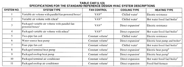
IECC 2012 contains 11 system types as detailed in Table C407.5.1(3):
The application of these systems is based on the selection criteria detailed in Table C407.5.1(2):
· Building type (Residential or non-residential or other)
· Cooling source (Water/ground or Air/none)
· Heating source (Electric or Heat pump or Fossil Fuel)
An IECC 2012 specific HVAC selection dialog has been included based on this new criteria and an IECC standard reference systems library has also been included.
While the selection dialog takes into account the selection criteria from Table C407.5.1(2) the following additional considerations should be noted when selecting the standard reference systems:
· Select "water/ground" if the proposed design system condenser is water or evaporatively cooled; select "air/none" if the condenser is air cooled. Closed-circuit dry coolers shall be considered air cooled. Systems utilizing district cooling shall be treated as if the condenser water type were "water." If no mechanical cooling is specified or the mechanical cooling system in the proposed design does not require heat rejection, the system shall he treated as if the condenser water type were "Air." For proposed designs with ground-source or groundwater-source heat pumps, the standard reference design HVAC system shall be water-source heat pump (System 6)
· Select the path that corresponds to the proposed design heat source: electric resistance, heat pump (including air source and water source), or fuel fired. Systems utilizing district heating (steam or hot water) and systems with no heating capability shall be treated as if the heating system type were "fossil fuel." For systems with mixed fuel heating sources, the system or systems that use the secondary heating source type (the one with the smallest total installed output capacity for the spaces served by the system) shall be modeled identically in the standard reference design and the primary heating source type shall be used to determine standard reference design HVAC system type
· Select the standard reference design HVAC system category: The system under "single-zone residential system" shall be selected if the HVAC system in the proposed design is a single-zone system and serves a residential space. The system under "single-zone nonresidential system" shall be selected if the HVAC system in the proposed design is a single-zone system and serves other than residential spaces. The system under "all other" shall be selected for all other cases.
Also based on the notes from the bottom of Table C407.5.1(1), it should be noted:
· Where no heating system exists or has been specified, the heating system shall be modeled as fossil fuel. The system characteristics shall be identical in both the standard reference design and proposed design
· The ratio between the capacities used in the annual simulations and the capacities determined by sizing runs shall be the same for both the standard reference design and proposed design
· Where no cooling system exists or no cooling system has been specified, the cooling system shall be modeled as an air-cooled single-zone system, one unit per thermal zone. The system characteristics shall be identical in both the standard reference design and proposed design.
· If an economizer is required in accordance with Table C403.3.1(1), and if no economizer exists or is specified in the proposed design, then a supply air economizer shall be provided in accordance with Section C403.4.1
Finally Table C407.5.1(1) specifies that the fuel type for the standard reference systems should be the same as that used in the proposed.
.
2 Purchased Heat / Purchased Chilled Water
Table C407.5.1(3)f Purchased Heat For systems using purchased hot water or steam, the boilers are not explicitly modeled and hot water or steam costs shall be based on actual utility rates.
Table C407.5.1(3)e Purchased Chilled Water. : For systems using purchased chilled water, the chillers are not explicitly modeled and chilled water costs shall be based as determined in Sections C407.3 and C407.5.2
3 Demand Control Ventilation
C403.2.5.1 is a mandatory requirement and requires that demand control ventilation (DCV) must be provided for each zone with spaces > 500 ft² and the average occupant load > 25 people/1000 ft² of floor area where the HVAC system has:
· An air-side economizer,
· Automatic modulating control of the outdoor air damper, or
· A design outdoor airflow > 3,000 cfm
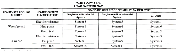
In ApacheHVAC, applicable IECC systems include pre-defined options for DCV. Users can enable DCV on these systems by checking the “Demand-controlled ventilation using zone CO2 sensors” box on the Zone Ventilation & Exhaust tab of the System Parameters dialog.
Figure 2: Zone Ventilation & Exhaust tab of the System Parameters dialog with DCV option highlighted.
For IECC standard reference systems in ApacheHVAC that do not include the option for DCV, modellers may use Prototype System 5b as an example for adding the damper and controllers to the standard reference system.
4 Economizers
Table C407.5.1(1) states that an economizer the same as the proposed is to be included in the standard reference in accordance with Section C403.4.1.
Whether or not the standard reference building HVAC system has an economizer depends on the climate zones (see Table C403.3.(1)). Climate zones 1A & 1B have no requirement. All other climate zones require economizers on cooling systems greater than or equal to 33,000 Btu/h, where the total capacity of all systems without economizers shall not exceed 300,000 Btu/h per building, or 20 percent of its air economizer capacity, whichever is greater.
There are exceptions as outlined in C403.3.1 e.g.
· Individual fan-cooling units with supply capacity see Table C403.3.1(1)
· Where > 25% of air designed to be supplied by the system is to spaces that are designed to be humidified > 35°F dew-point temperature to satisfy process needs
· Systems that serve residential spaces where system capacity is < 5 times the requirement in Table C403.3.1(1)
· Systems expected to operate < 20 hours/week
· Where use of outdoor air for cooling will affect supermarket open refrigerated casework systems
· Where cooling efficiency meets or exceeds efficiency requirements in Table C403.3.1(2)
When an economizer is required, it must have a high-limit shutoff switch as per C403.3.1.1.3(1). There are many allowed control types per climate zone, but one that senses dry-bulb temperature and shuts off economizer operation (reduces outdoor air to the minimum required for ventilation) when the outdoor temperature exceeds the values shown Table C403.3.1.1.3(2) is common to all climate zones. The specific high-limit shutoff temperature depends on the climate zone.
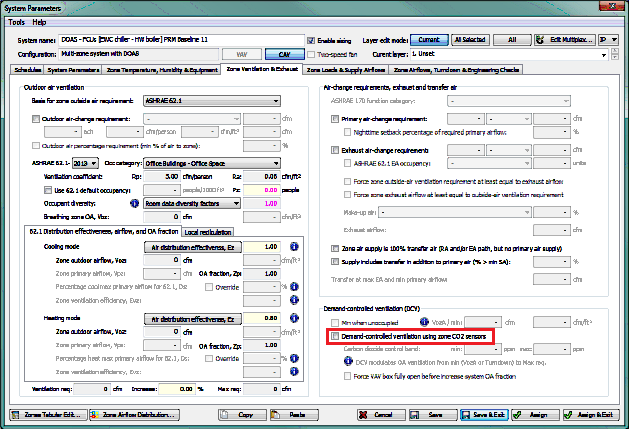
In ApacheHVAC, all applicable IECC standard reference systems have an economizer with the dry-bulb temperature high-limit set to 70°F by default. The high-limit temperature can be changed (or the economizer can be changed/disabled) by accessing the System Parameters tab of the System Parameters dialog.
Figure 4: System Parameters tab of the System Parameters dialog with economizer option highlighted
Note: Other economizer types are allowed and can also be modelled from the System Parameters tab of the System Parameters dialog.
5 Exhaust Air Energy Recovery
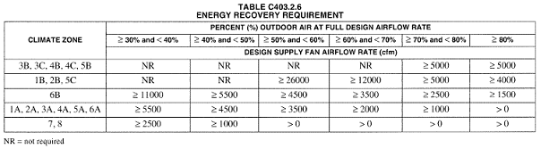
Energy recovery ventilation systems as detailed in section C403.2.6 are mandatory. They apply based on climate zone, percent outdoor and airflow rates greater than a certain value as per Table C403.2.6
The energy recovery system shall have a recovery effectiveness of at least 50%. The energy recovery system does not negate the requirement for an outdoor air economizer when an economizer is required for the standard reference building system. Furthermore, the baseline building system must permit air to bypass the energy recovery system during economizer operation. There are exceptions to the heat recovery requirements for specific climates, see Exceptions in C403.2.6.
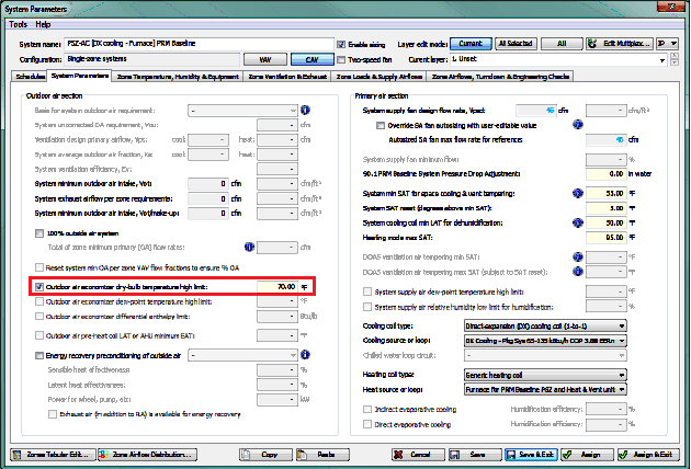
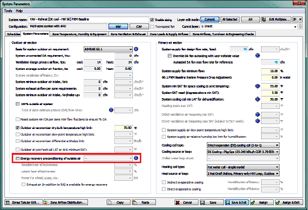
In ApacheHVAC, all applicable IECC standard reference systems include the option for airside energy recovery but it is disabled by default. To engage the pre-defined energy recovery, check the “Energy recovery preconditioning of outside air” box on the System Parameters tab of the System Parameters dialog.
Figure 5: System Parameters tab of the System Parameters dialog with energy recovery option highlighted
6 Equipment Efficiencies
The minimum mandatory efficiencies for HVAC equipment shown in section C403.2.3 must be used for the applicable equipment in the standard reference building design. This includes any part load efficiencies if these are specified. Minimum HVAC equipment efficiencies are included in the IECC systems library.
7 Hot Water Supply Temperature Reset
Notes to Table C407.5.1(3) state that hot water supply temperature shall be modeled at 180°F design supply temperature and 130°F return temperature. Piping losses shall not be modeled in either building model. Hot water supply water temperature shall be reset in accordance with Section C403.4.3.4 i.e.
Hydronic systems greater than or equal to 300,000 Btu/h (87 930 W) in design output capacity, supplying heated or chilled water to comfort conditioning systems shall include controls that have the capability to:
· Automatically reset the supply-water temperatures using zone-return water temperature, building-return water temperature, or outside air temperature as an indicator of building heating or cooling demand. The temperature shall be capable of being reset by at least 25 percent of the design supply-to-return water temperature difference; or
· Reduce system pump flow by at least 50 percent of design flow rate utilizing adjustable speed drive(s) on pump(s), or multiple-staged pumps where at least one-half of the total pump horsepower is capable of being automatically turned off or control valves designed to modulate or step down, and close, as a function of load, or other approved means.
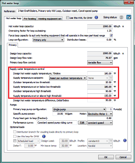
For applicable IECC standard reference systems, the hot water supply temperature shall be reset based on the outdoor dry-bulb temperature. When the outdoor temperature is 20°F and below, the supply temperature shall be a constant 180°F. When the outdoor temperature is 50°F and above, the supply temperature shall be 150°F. When the outdoor temperature is between 20°F and 50°F, the supply temperature shall be ramped in a proportional manner between 180°F and 150°F.
Figure 6: Default hot water loop supply water temperature control settings
8 Hot Water Pumps
Notes to Table C407.5.1(3) state that pump system power for each pumping system shall be the same as the proposed design. If the proposed design has no hot water pumps, the standard reference design pump power shall be 19 W/gpm (equal to a pump operating against a 60-foot head, 60-percent combined impeller and motor efficiency). The hot water system shall be modeled as primary only with continuous variable flow. Hot water pumps shall be modeled as riding the pump curve or with variable speed drives when required by Section C403.4.3.4.
Default hot water loops for IECC Systems in ApacheHVAC are primary-only variable flow, have a specific pump power of 19 W/gpm, and use a constant speed pump curve. When the requirement changes based on specifics in the code users will need to change the pump performance curve to variable speed using the pull-down menu in the hot water loop dialog.
9 Chiller Selection
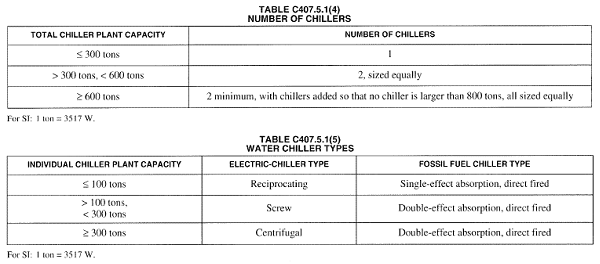
Notes to Table C407.5.1(3) state that the standard reference design's chiller plant shall be modeled with chillers having the number as indicated in Table C407.5.1(4) as a function of standard reference building chiller plant load and type as indicated in Table C407.5.1(5) as a function of individual chiller load. Where chiller fuel source is mixed, the system in the standard reference design shall have chillers with the same fuel types and with capacities having the same proportional capacity as the proposed design's chillers for each fuel type.
For applicable IECC standard reference systems the number and type of electric water-cooled chillers to be modelled is determined as a function of building peak cooling load. When the building peak cooling load is less than or equal to 300 tons, a single screw chiller is required. When the building peak cooling load exceeds 300 tons but is not larger than 600 tons, two equally sized screw chillers are to be used.
For models where the standard reference building peak cooling load exceeds 600 tons, a minimum of 2 equally sized centrifugal chillers must be used. No chiller, however, can be greater than 800 tons so the addition of more equally sized chillers may be required on large projects.
Applicable IECC standard reference systems in ApacheHVAC include a single water-cooled centrifugal chiller by default. For baseline buildings where the peak cooling load does not exceed 300 tons, no additional chillers are needed, but the chiller curve selection will need to be updated to a screw-type chiller.
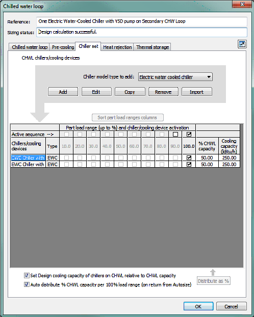
If the peak cooling load in the standard reference building exceeds 300 tons but is not larger than 600 tons, users can add a second chiller to the chilled water loop by using the copy button on the Chiller set tab of the Chilled water loop dialog. Both chillers will need screw curve sets (not the default centrifugal curves) so it is recommended that this change be made prior to using the Copy button. Users should ensure that the chillers are equally sized and can do so quickly by setting the % CHWL capacity to 50% for each chiller.
Figure 8: Chiller set tab of the Chilled water loop dialog illustrating two equally sized chillers serving a peak building cooling load of 500 tons
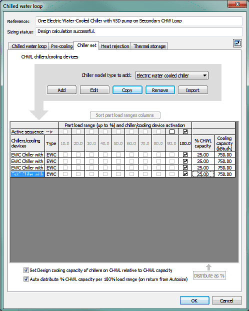
If the peak cooling load in the baseline building exceeds 600 tons, users can copy the default chiller until there are enough chillers on the chilled water loop to satisfy the building peak cooling load without any chiller exceeding 800 tons in size. Every loop must have at least 2 chillers and all chillers must be equally sized.
For example, a model where the baseline building peak cooling load is 700 tons requires 2 x 350 ton chillers. Where the standard reference building peak cooling load is 3,000 tons, the model requires 4 x 750 ton chillers.
Figure 9: Chiller set tab of the Chilled water loop dialog illustrating four equally sized chillers serving a peak building cooling load of 3,000 tons
It should be noted that the default baseline chiller curves come from the generic curve sets in DOE-2.2 and are based on entering condenser temperature (ECT). The manufacturer-specific curves available to users in the Performance Curve library are based on leaving condenser temperature (LCT). If LCT curves are used for the proposed chillers, users may consider following the steps below to better isolate the results of actual differences in the baseline and proposed chiller plants (e.g., differences in chiller COP, design sizing, supply water temperature set points, etc.):
· Define appropriate curve set for proposed chiller & test via simulation to confirm that the chiller is modeling as expected.
· Save a copy of that chiller with a new name for the standard reference chiller.
· Revise the COP at the rated condition to match the IECC requirements for minimum chiller performance in Chapter 4.
· Confirm that the IPLV is at least that required for IECC Data needed for IPLV calculations can be found by reading the values at the four required load ranges from the 2D plots in the ApacheHVAC Performance Curves Library interface. Derivation of IPLV for each chiller curve set will be included in a future release of the VE.
10 Chilled Water Supply Temperature Reset
Notes to Table C407.5.1(3) state that chilled water supply temperature shall be modeled at 44°F design supply temperature and 56°F return temperature. Piping losses shall not be modeled in either building model. Chilled water supply water temperature shall be reset in accordance with Section C403.4.3.4. i.e.
Hydronic systems greater than or equal to 300,000 Btu/h (87 930 W) in design output capacity, supplying heated or chilled water to comfort conditioning systems shall include controls that have the capability to:
· Automatically reset the supply-water temperatures using zone-return water temperature, building-return water temperature, or outside air temperature as an indicator of building heating or cooling demand. The temperature shall be capable of being reset by at least 25 percent of the design supply-to-return water temperature difference; or
· Reduce system pump flow by at least 50 percent of design flow rate utilizing adjustable speed drive(s) on pump(s), or multiple-staged pumps where at least one-half of the total pump horsepower is capable of being automatically turned off or control valves designed to modulate or step down, and close, as a function of load, or other approved means.
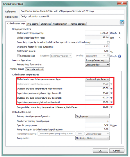
For applicable IECC standard reference systems, the chilled water temperature shall be reset on an hourly basis, based on the outdoor air temperature. When the outdoor temperature is 80°F or greater, the supply temperature shall be a constant 44°F. When the outdoor temperature is 60°F or below, the supply temperature shall be 56°F. When the outdoor temperature is between 60°F and 80°F, the supply temperature shall ramp between 44°F and 56°F in a proportional manner. If there is dehumidification requirement of the cooling coils, the maximum reset of chilled water temperature should be calculated according to the dehumidification requirement and cooling coils performance.
Figure 10: Default chilled water loop supply water temperature control settings
11 Chilled Water Pumps
Notes to Table C407.5.1(3) state that pump system power for each pumping system shall be the same as the proposed design. If the proposed design has no chilled water pumps, the standard reference design pump power shall be 22 W/gpm (equal to a pump operating against a 75-foot head, 65-percent combined impeller and motor efficiency). The chilled water system shall be modeled as primary-only variable flow with flow maintained at the design rate through each chiller using a bypass. Chilled water pumps shall be modeled as riding the pump curve or with variable-speed drives when required in Section C403.4.3.4.
Default chilled water loops for IECC Systems in ApacheHVAC are primary only configuration with constant flow on the primary loop. The primary loop has a specific pump power of 22 W/gpm with the pump riding the pump curve. When the requirement changes based on specifics in the code users will need to change the pump performance curve to variable speed using the pull-down menu in the chilled water loop dialog.
12 Heat Rejection
Notes to Table C407.5.1(3) state that the heat rejection device shall be an axial fan cooling tower with two-speed fans if required in Section C403.4.4.
In ApacheHVAC, applicable IECC systems have a cooling tower with a two-speed axial fan by default. The fan power is calculated based on heat rejection load and the default fan electric input ratio. Users should edit the cooling tower fan power to meet the requirements of IECC.
The code also states that the condenser water design supply temperature shall be 85°F or 10°F approach to design wet-bulb temperature, whichever is lower, with a design temperature rise of 10°F. The tower shall be controlled to maintain a 70°F leaving water temperature where weather permits, floating up to leaving water temperature at design conditions.
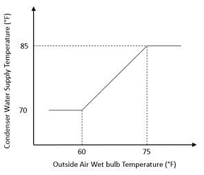
Applicable IECC systems have an 85°F design condenser water loop supply temperature by default, with a 10°F design temperature difference. A formula profile is used to control condenser water loop supply temperature. The following formula resets the condenser water loop supply temperature setpoint based upon outside air wetbulb using the following ramp function:
ramp(twb,60,70,75,85)
Where outdoor weather conditions permit the cooling tower to achieve the condenser water supply temperature setpoint, this formula will drive the cooling tower to maintain a 10°F approach. When the outside air wetbulb temperature is 60°F or lower, the condenser water supply temperature setpoint will be 70°F. Above 75°F outside air wetbulb, the setpoint will be 85°F. When the outside air wetbulb temperature is between 60°F and 75°F, the condenser water supply temperature setpoint will vary proportionally between 70°F and 85°F. This operation is represented in the graph below:
The code requires that the standard reference pump power for each pumping system shall be the same as the proposed design. If the proposed design has no condenser water pumps, the standard reference design pump power shall be 19 W/gpm (equal to a pump operating against a 60-foot head, 60-percent combined impeller and motor efficiency). This is the default specific pump power in ApacheHVAC for IECC systems.
The standard also requires that each chiller shall be modelled with separate condenser water and chilled water pumps interlocked to operate with the associated chiller. By default, ApacheHVAC includes a single chilled water pump and single condenser water pump. Users should change this setting when multiple chillers exist. This can be done by changing the Primary circuit pump configuration pull-down menu on the Primary circuit sub-tab of the Chilled water loop tab and the Condenser loop pump configuration on the Condenser water loop sub-tab of the Heat rejection tab.