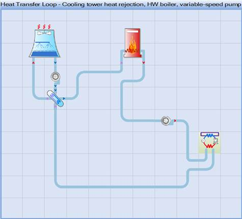
Select a Heat transfer loop to serve as the heat source and heat sink for the VRF ‘outdoor’ unit (which, in this case is really a water-source unit that may be located within the building). A typical Heat Transfer Loop (HTL) for heat acquisition and rejection from multiple water-source VRF systems is shown below. Multiple VRF systems coupled to the HTL can independently add and remove heat as needed to meet building loads. The HTL can thus transfer heat rejected by one or more VRF systems operating in cooling mode to other VRF systems operating in heating mode. Typically, the temperature of this loop is allowed to ‘float’ within a substantial range. The boiler adds heat only if the loop gets unusually cold and the cooling tower rejects heat to the outdoor environment only if the loop gets too warm.
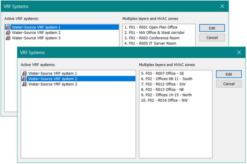
Figure 3-136: VRF Systems list dialog showing three water-cooled VRF systems on a Heat Transfer Loop (HTL). This dialog becomes available when there is more than one VRF system associated with a single airside system (e.g., when single DOAS provides ventilation to a set of zones heated and cooled by multiple VRF systems). It is accessed by clicking the VRF icon on the HTL, as shown above, to facilitate selection of the VRF system to edit.
In the example above, a single outside air ventilation system (DOAS) is serving zones that are heated and cooled by three VRF systems. The list of HVAC zones on numbered multiplex layers on the right side of the dialog are those served by the currently selected VRF system. Thus the user has an indication of which VRF system they are about to edit prior to clicking the Edit button.