Shading devices of three kinds – internal, external and local – may be attached to glazed constructions. This is a quick way to specify shading features to all instances of a glazing construction. The results of the shading calculations performed for these shading devices are combined with those carried out by SunCast.
The three types of shading device are suitable for representing the following types of shading:
Internal: curtains, blinds.
External: shutters, louvres, brise soleils.
Local: side-fins, overhangs, balconies, window recesses.
Internal Shading
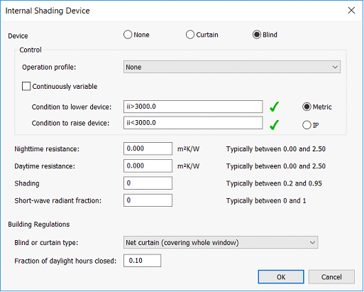
The input dialog window for an internal shading device is shown below. Descriptions of the data fields are given below.
Figure 19 Internal Shading Device dialog
Device:
Selecting Curtains or Blinds activates the device and allows the parameters to be edited. No distinction is made between curtains and blinds in terms of the performance of the device.
Control:
Parameters in this group control the state (raised or lowered) of the shading device.
Continuously variable:
When enabled, the shading device operates in continuously variable mode. In this mode, the shading device can occupy any state in a continuous range between fully lowered and fully raised. The state depends on evaluation of the operation profile. In this mode, conditions to raise and lower the shading device are not applicable.
When disabled, the shading device operates in discrete mode. In this mode, the shading device can occupy two states: fully lowered and fully raised. No intermediate state is permitted in this mode. The state depends on evaluation of the operation profile and of the conditions to lower and raise the device.
Operation profile:
In continuously variable mode, the operation profile is a percentage profile specifying the time of the shading device operation, with 100% corresponding to fully lowered and 0% corresponding to fully raised.
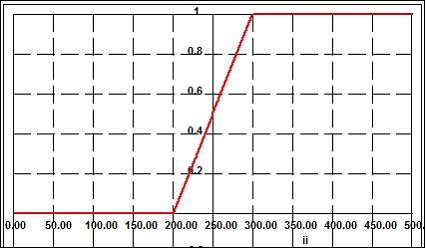
The incident irradiance variable (‘ii’) can be entered into a formula profile configuration. A typical profile gt(ii,250,100) would ramp the profile from 200 W/m2 (fully raised) to 300 W/m2 (fully lowered) in Metric mode.
In discrete mode, the operation profile is a percentage profile specifying the timing of the shading device operation. Percentage values greater than 50% are interpreted as ‘on’ and other values as ‘off’. When the profile is on, the device operates (i.e. is lowered into position). When the profile is off, or set to ‘none’, the device is controlled by logical conditions to raise and lower the device, as specified by the following two parameters. These parameters are described assuming discrete mode is in effect.
Condition to Lower Device:
This parameter comes into play when the operation profile is off. The shading device starts operating (i.e. is lowered into position) when the condition to lower device evaluates to true (a value greater than or equal to 0.5) and the condition to raise device evaluates to false (a value less than 0.5). The syntax for this condition, and its counterpart described below, is the same as for formula profiles. It is usual (though not required) to use the incident irradiance (‘ii’) variable in these parameters.
Condition to Raise Device:
This parameter comes into play when the operation profile is off. The shading device stops operating (i.e. is raised) when the condition to raise device evaluates to true (a value greater than or equal to 0.5). If both conditions evaluate to false (a value less than 0.5), the shading device remains in its previous state. If both conditions evaluate to true (a value greater than or equal to 0.5), the shading device is raised.
In order to simulate a control mechanism controlled entirely by the operation profile, ensure that condition to lower device is set to 0.0 and condition to raise device is set to 1.0.
Metric/IP:
The variables in the conditions to raise and lower device have the specified units. This is independent of the global system of units specified in User Preferences.
The incident irradiance variable (‘ii’) is entered as W/m2 for Metric and Btu/h/ft2 for IP units.
Night-time Resistance:
The additional thermal resistance (if any) associated with the device when it is in operation at night (taken to be when the sun is below the horizon). This parameter allows you to make allowance for the night-time closing of curtains or blinds.
A value of zero is appropriate in most cases. Net curtains and most types of blind have minimal insulation effect on the glazing. They can therefore be ignored for most applications. However, the effect of heavyweight curtains and blinds should be included.
Daytime Resistance:
The additional thermal resistance (if any) associated with the device when it is in operation during the day (taken to be when the sun is above the horizon). This extra resistance affects not only the U-value, but also the retransmitted component of absorbed solar radiation.
A value of zero is appropriate in most cases. Net curtains and most types of blind have minimal insulation effect on the glazing. Their thermal effect can therefore be ignored for most applications. However, the effect of heavyweight curtains and blinds should be included.
Shading Coefficient:
Blinds and curtains reduce solar penetration into the space by reflecting and absorbing short-wave solar radiation. A proportion of the absorbed heat (sometimes called re-transmitted heat) is transferred into the room by convection and long-wave radiation.
The shading coefficient specifies the degree to which the blind reduces the short-wave component of room solar gain that passes through the glazing panes. A value of 1 means no shading and a value of 0 perfect shading. Typical values are listed in Table 8 of the Apache Tables document. The internal blind is not considered to affect the long wave radiation and convective heat transfer from the glazing to the room.
If the solar transmittance (T) and absorptance (A) are known for the blind, values for the shading coefficient (SC) and short-wave radiant fraction (SWRF) can be obtained using:
SC = T + 0.87*A
SWRF = T/SC
These formulae apply to a blind consisting of a single sheet of material, such as a roller blind or a closed slatted blind. They can be applied to open or partially open slatted blinds if an allowance is made in the T and A values for inter-reflection between the slats.
Short-Wave Radiant Fraction:
The short-wave radiant fraction specifies the proportion of the room heat gain associated with the blind that passes through it as short-wave radiation.
Typical values are listed in Table 8 in the Apache Tables document. A method for deriving values from blind properties is described under Shading Coefficient.
Building Regulations L1:
Used for defining local shading in conjunction with Part L1 for dwellings. See the SAP 2005 document for more details on these settings in relation to overheating.
External & Local Devices
External Shading
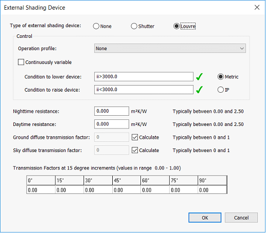
The input dialog window for an external shading device such as a shutter, louvre or brise soleil is shown below. Descriptions of the data fields are given below.
Figure 20 External Shading Device dialog
Device:
Selecting Shutters or Louvres activates the device and allows the parameters to be edited. No distinction is made between shutters and louvres in terms of the performance of the device.
Control:
Parameters in this group control the state (raised or lowered) of the shading device.
Continuously variable:
When enabled, the shading device operates in continuously variable mode. In this mode, the shading device can occupy any state in a continuous range between fully lowered and fully raised. The state depends on evaluation of the operation profile. In this mode, conditions to raise and lower the shading device are not applicable.
When disabled, the shading device operates in discrete mode. In this mode, the shading device can occupy two states: fully lowered and fully raised. No intermediate state is permitted in this mode. The state depends on evaluation of the operation profile and of the conditions to lower and raise the device.
Operation profile:
In continuously variable mode, the operation profile is a percentage profile specifying the time of the shading device operation, with 100% corresponding to fully lowered and 0% corresponding to fully raised. The incident irradiance variable (‘ii’) can be entered into a formula profile configuration. A typical profile gt(ii,250,100) would ramp the profile from 200 W/m2 (fully raised) to 300 W/m2 (fully lowered) in Metric mode.
In discrete mode, the operation profile is a percentage profile specifying the timing of the shading device operation. Percentage values greater than 50% are interpreted as ‘on’ and other values as ‘off’. When the profile is on, the device operates (i.e. is lowered into position). When the profile is off, or set to ‘none’, the device is controlled by logical conditions to raise and lower the device, as specified by the following two parameters. These parameters are described assuming discrete mode is in effect.
Condition to Lower Device:
This parameter comes into play when the operation profile is off. The shading device starts operating (i.e. is lowered into position) when the condition to lower device evaluates to true (a value greater than or equal to 0.5) and the condition to raise device evaluates to false (a value less than 0.5). The syntax for this condition, and its counterpart described below, is the same as for formula profiles. It is usual (though not required) to use the incident irradiance (‘ii’) variable in these parameters.
Condition to Raise Device:
This parameter comes into play when the operation profile is off. The shading device stops operating (i.e. is raised) when the condition to raise device evaluates to true (a value greater than or equal to 0.5). If both conditions evaluate to false (a value less than 0.5), the shading device remains in its previous state. If both conditions evaluate to true (a value greater than or equal to 0.5), the shading device is raised.
In order to simulate a control mechanism controlled entirely by the operation profile, ensure that condition to lower device is set to a formula which will always evaluate to 0.0 and condition to raise device is set to a formula which will always evaluate to 1.0.
Metric/IP:
The variables in the conditions to raise and lower device have the specified units. This is independent of the global system of units specified in User Preferences.
The incident irradiance variable (‘ii’) is entered as W/m2 for Metric and Btu/h/ft2 for IP units.
Night-time Resistance:
The additional thermal resistance (if any) associated with the device when it is in operation at night (taken to be when the sun is below the horizon). This parameter allows you to make allowance for the night-time closing of shutters. A value of zero is appropriate in most cases.
Daytime Resistance:
The additional thermal resistance (if any) associated with the device when it is in operation during the day (taken to be when the sun is above the horizon). This extra resistance affects not only the U-value, but also the retransmitted component of absorbed solar radiation. A value of zero is appropriate in most cases.
Ground diffuse transmission factor:
The degree to which the ground is shaded by the device as viewed from the glazing construction. This affects the amount of diffuse ground-scattered solar radiation incident on the window. Ticking the Calculate check box sets a default value of 1.
Sky diffuse transmission factor:
The degree to which the sky is shaded by the device as viewed from the window. This affects the amount of diffuse solar radiation incident on the window from the sky. Ticking the Calculate calculates a value for this parameter as a suitably weighted average of the transmission factors for direct solar radiation.
Transmission Factors at 15 degree increments:
Values of the transmittance of the shading device for direct solar radiation, at 15 degree angular increments. The angle in question is the solar altitude measured in a vertical plane perpendicular to the glazing construction.
Local Shading
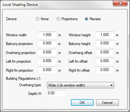
The input dialog window for local shading features such as projections and window recesses is shown below. Descriptions of the data fields are given below.
Figure 21 Local Shading Device dialog
Device:
Selecting Projections or Window Recesses activates the device and allows the parameters to be edited. No distinction is made between projections and window recesses in terms of the performance of the device. Enter the value 0 for parameters relating to any shading features that are not present.
Window width:
The width of the windows to which the construction is to be assigned. The shading calculations will only be correct if applied to a rectangular window of the given dimensions.
Window height:
The height (top to bottom) of the windows to which the construction is to be applied. The shading calculations will only be correct if applied to a rectangular window of the given dimensions.
Balcony projection:
If there is a balcony, enter the distance it projects from the plane of the window.
Balcony height:
The height of the top edge of the balcony measured from the lower edge of the window.
Overhang projection:
If there is an overhang or recess soffit, enter the distance it projects from the plane of the window.
Overhang offset:
The distance between the overhang and the top of the window.
Left fin projection:
If there is a left side-fin or a left wall of a window recess (as viewed from the outside), enter the distance it projects from the plane of the window.
Left fin offset:
The distance between the left fin or left recess wall from the adjacent window edge.
Right fin projection:
If there is a right side-fin or a right recess wall (as viewed from the outside), enter the distance it projects from the plane of the window.
Right fin offset:
The distance between the right fin or right recess wall from the adjacent window edge.
Building Regulations L1:
Used for defining local shading in conjunction with Part L1 for dwellings. See the SAP 2005 document for more details on these settings in relation to overheating.