Prototype HVAC systems: Common features
The pre-defined prototype systems in ApacheHVAC provide autosizing capability, examples of various system configurations, and a starting point for users who wish to create custom configurations—either from one of the prototypes or using these as an example.
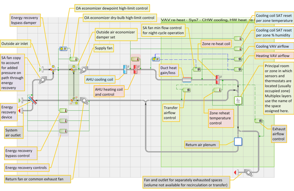
Figure 1 - 8 : Many elements shown here are common to other pre-defined prototype systems. The sections below describe these and many others.
System-level or air handler vs. zone-level elements
For single-zone systems, the entire system is multiplexed, allowing numerous single-zone systems to be set up and autosized via multiple layers within a single airside network view and multiple rows within a single zone-level Loads Data spreadsheet.
For multi-zone systems, each airside network represents just one air handler and the associated zones. The system-level or air handler components are located on the left and outside of the multiplex boundary, whereas the zone-level components and controls are located within the multiplex boundary.
Outside air intake and outlet
All system networks must have at least one air intake and outlet; however, a system can have more than one of either (see further guidance in section 1.4: System Modeling Fundamentals and Appendix A: Rules for Air Flow Specification). Generally, the predefined systems have inlets for both direct outside air supply and an optional path through an airside energy recovery device. These could be combined, but there is no need for or benefit in doing so. Similarly, there are outlet at the air handler and separate exhaust fan that could be combined. The separation of these in the pre-defined configuration is intended simply to make clear that the separate exhaust is air that is not available for recirculation, transfer air, etc.
Airside energy recovery
The airside energy recovery component can be used to model a broad range of devices. In the pre-defined systems, it is most often …
Energy recovery device
Cooling mode control of recovery temperature target
Heating mode control of recovery temperature target
Energy recovery bypass damper
Bypass damper control
Energy recovery static pressure
Energy recovery and bypass damper section
This system element is common to all of the pre-defined multi-zone systems, and provides for recovery and heating and cooling energy for pre-conditioning of outside air when it is enabled.
· Midband for damper modulation and set point for changeover from heating to cooling mode for energy recovery target are the airflow-weighted average midpoint between heating and cooling room temperature setpoints for all zones on the same system. If the heating and cooling setpoints for the zones on the system are 68 °F and 76 °F, respectively, then the midband/setpoint value returned to these controllers will be 72 °F.
· For the Energy Recovery mode controls, this is the return air temperature, subject to a deadband or hysteresis, above or below which the default configuration assumes the majority of zones on the system are in cooling vs. heating mode. The majority, in this case, is with respect to total conditioned/ventilation air volume on the system, as the sensors for these controls see only the combined return air temperature. If the RA temperature is below the threshold minus half the deadband (e.g., 71 °F for the example above with a 2 °F deadband), the zones are, on average given the volume return air from each, assumed to be in heating mode, and the heating mode temperature target in SC5 applies. If the RA temperatures is above the threshold plus half the deadband (e.g., 73 °F), the zones are, on average, assumed to be in cooling mode, and the cooling mode temperature target in SC4 applies.
· For the Energy recovery bypass damper SAT target, the same value, is the midband for proportional control of the mixed-air target temperature downstream of continuously modulated bypass damper. As the return air gets warmer, indicating the zones are collectively warmer, the temperature target for damper modulation is steadily reduced over the bandwidth of sensed values. For the 72°F the example above with a 4°F defaults bandwidth, the bypass temperature target will be at its maximum value when the sensed RA temperature is 70°F and will be at its minimum value when the sensed RA temperature is 74°F, thus minimizing undesirable heating or cooling load associated with outside air while maximizing fee cooling when a warmer RA temperature indicates the zones are on average (by volume) 74°F or warmer (i.e., they are in cooling mode).
Autosizing values in the energy recovery device and bypass damper controllers are determined as follows:
Target temperatures for the energy recovery bypass damper and for the heating and cooling for modes of the energy recovery device are also based upon the return air temperature. The intent here is to maximize economizer hours. The ER component has a leaving air temperature target set as follows:
· The LAT target for ER is set unachievable low value (for “coolth” recovery) when the temperature of the return air is above the mid-point between the flow-weighted average of heating and cooling setpoints for all zones on the system. This condition suggests that the “average” conditioned volume of air for any zone on the system is in cooling mode.
· The LAT target for ER is set unachievable high value (for heat recovery) when the temperature of the return air is below the mid-point between the flow-weighted average of heating and cooling setpoints for all zones on the system. This condition suggests that the “average” conditioned volume of air for any zone on the system is in heating mode.
· Both of the above are subject to a 2°F deadband that provides hysteresis—i.e., the RA temp must drop to 1 °F below the flow-weighted average setpoint mid value before the ER will switch from coolth recovery to heat recovery.
· The ER bypass damper uses the same flow-weighted average of heating and cooling setpoints for all zones on the system as a proportional midband to adjust the bypass damper mixed-air target from the same unachievable high value (for ER heat recovery target) to the same unachievable low value (for ER “coolth” recovery target). Thus when the RA is decidedly warm (suggesting the zones are, on average, very warm) the bypass damper will modulate to provide the coolest mix of air from the combination of the direct OA vs. ER paths. Conversely, when the RA is decidedly cool (suggesting the zones are, on average, very cool) the bypass damper will modulate to provide the warmest mix of air from the combination of the direct OA vs. ER paths.
· The flow-weighted average of midpoint between heating and cooling setpoints for all zones on the system is just that:
o The spreadsheet figures the midpoint between heating and cooling setpoints for each zones on the system.
o Each of these values is then multiplied by the max design flow rate to the corresponding zone.
o These values are added up, and then divided by the total flow rate for all zones to get the flow-weighted value for the midpoint between heating & cooling setpoints.
· The resulting behavior should be that the ER component plus bypass damper will provide a relatively ideal selection of air as direct OA vs. OA with ER, selecting from the relative temperatures of the air on these two paths with its logic driven by the temperature of the RA.
· If your swimming pool is very large relative to other spaces on the system, it’s higher cooling setpoint will have a proportionately large influence upon the heating and cooling targets for the ER component and bypass.
Note that the energy recovery heating and cooling mode target temperatures are intended to be unattainable targets, just beyond the reach of the capability of the device to pre-heat or pre-cool the incoming outdoor air with recovered heat or “coolth”. For the example above, when in heating mode (based upon a sensed RA temperature of 71°F or less) the energy recovery would not be expected to be able to heat the outside air all the way to 70°F with heat recovered from return/exhaust air that is itself 71°F or cooler. Similarly, the energy recovery would certainly not be expected to cool the outside air all the way to 50 °F by rejecting heat from it to the return/exhaust air that is itself 73°F or warmer.
SC5 uses the same values at Min and Max signal as the energy recovery targets in SC4 and SC5. For the controllers on the energy recovery device, SC4 and SC5, the targets could be more extreme with no effect, as they are almost certainly unattainable. However, if the target temperatures at the high and low ends of the proportional control band for the bypass damper are set to overly extreme values, this will have the effect of making the useful part of the proportional band ramp very quick (over a nary range of sensed values) from the lowest to the highest attainable values, or vice versa.
The most important number in these three controllers is the setpoint in the energy recovery mode controls and midband value for the proportional control in the bypass and the bypass damper control, as it determines the changeover from heating to cooling logic for energy recovery based upon the RA temperature.
Note that, apart from the energy-intensive intentional reheat after sub-cooling to dehumidify the intake air, it is unlikely you would set the LAT for the AHU heating coil in a pre-defined system configuration to a value warmer than the lowest LAT for the cooling coil immediately upstream of it (e.g., 55 °F): If set to a warmer LAT, the heating coil will simply consume energy reheating the air just cooled by the cooling coil. If, however, you chose to replace the fixed-temperature controller on the AHU heating coil with one that, for example, used a sensor to re-set the SAT according to zone temperatures, etc., then you would replace the autosized controller with one of your own.
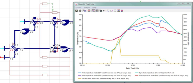
The following graph of intake air flow rate and temperatures on either side of the energy recovery device on a hot summer day.
Teal = outside air (node 21)
Blue = intake air after the energy recovery device (node 22)
Purple = return/exhaust air (node 40)
Red = exhaust air after receiving rejected heat from the intake air (node 41)
Gold = intake air flow rate (node 21)
It can be seen that the intake air matches the outside air temperature until the point at which the outside air is actually warmer than the exhaust air from the building. At this crossover point, the energy recovery device begins, by virtue of this temperature differential, to transfer heat from the incoming outdoor air to the outgoing exhaust air. The effect increases with the delta-T in keeping with the heat exchanger effectiveness input. This rejection of unwanted heat continues until the system airflow is reduced to zero at the end of the day. It can also be seen that in the early evening the temperature of the intake air rises with a rise in the temperature of the return/exhaust air, and thus also a drop in useful delta-T and the rate of heat rejection to the exhaust.
Outside air ventilation damper and airside economizer
Minimum ventilation rate
The minimum outside ventilation rate is set for pre-defined systems within the mixing damper S1: OA Economizer - min OA per 62.1. While this component includes “per 62.1” in its name, the 62.1 calculations are used only if the user asks for this within the 62.1 OA Calcs tab of the Loads Data spreadsheet and is otherwise the ventilation rate set up by the user in the VE thermal templates/Space Data or in this component. The default HVAC EP1 - Economizer (Timeswitch: Sys 3--8) profile used in the OA damper set is linked to the System Schedules dialog and provides means of setting the minimum OA value to zero in the unoccupied hours (depending upon the operating/set-back strategy selected in this dialog for unoccupied hours). As described below, this profile can be modified to modulate the minimum OA value for scheduled changes in ventilation rate and certain similar DCV strategies.
Demand-controlled ventilation
For systems with demand-controlled ventilation (DCV), building codes may permit the use of a modulated minimum outside air setting or even a minimum setting of zero outside air. Depending on what type of DCV control is used, however, the OA ventilation/economizer damper component will most often still have a set design minimum airflow value. How this is modulated depends upon the type of DCV control.
-
Occupancy schedule: For systems that serve spaces with dependably predictable occupancy schedules, a modulating profile (ranging from 1.0 to some fraction of 1.0) can be used to reduce the OA ventilation rate to a fraction the design airflow set point when permitted by reduced occupancy. This is similar to the standard profile that is used to reset the OA damper to zero flow during scheduled unoccupied hours, such as nights and weekends. When starting with a pre-defined prototype system, therefore, the modulating profile for schedule-based DCV should be either a modification or user-defined replacement for the default HVAC EP1 - Economizer (Timeswitch: Sys 3--8) profile used in the OA damper set.
Note that changing the name of this profile precludes it being edited along with other HVAC profiles via the System Schedules dialog. Simply modifying it maintains the connection, but can be overwritten when the System Schedule inputs are subsequently saved by clicking OK in the System Schedules dialog.
-
Occupancy sensors: Because any model of building operation will use schedule profiles to simulate variations in occupancy for rooms and thermal zones, this type of DCV will also be modeled using a schedule-based modulating profile in the OA damper. The one difference from the profile used to represent spaces with occupancy sensors is that it will most often be appropriate to create a modulating profile that represents some overlap and some diversity in the timing of occupancy for spaces on the system. This should reflect the building program.
-
CO
2 sensors – single-stage control: This type of control adjust the system-level outside air setting based upon a “critical zone” (the zone with the highest sensed CO
2 value). So long as there are CO
2 sensors and a means of modulating the mix of outside vs. recirculated air, this can be used on single- or multi-zone systems with either variable or constant-volume airflow.
This is modeled via a zone-level controller with CO2 sensor that “votes” on the position of the system OA damper. Whichever zone votes for the most open position of the OA damper wins the vote, and thus becomes the “critical zone,” as it is determining the system OA damper position at that time. In the cases of a single-zone system, the percentage OA is simply modulated in response to the zone CO2 concentration—no voting is required.
The OA modulation is performed via a damper component providing a bypass around the main OA economizer damper. In a real-world application, these would most likely be one in the same. The separate damper set is used in the system model simply to allow the controlled variable to be a target leaving air temperature for the economizer operation and a percentage damper opening to the left branch of the component for the DCV control (one damper component cannot be controlled according to more than one controlled variable type). The two dampers are, in effect, one damper with two overlapping modes and means of control.
-
CO
2 sensors – dual-stage control: The two-stage DCV control is appropriate in multi-zone VAV systems for which the primary air supply is at least partially recirculated air and there is both a zone-level damper to modulate primary airflow and a system-level outside-air damper.
The first stage forces the VAV damper for any given zone to open more, to the extent it is not already fully open, to minimize CO2 accumulation as the CO2 level in that zone approaches the set CO2 ppm threshold. Once the VAV damper is fully open, if the CO2 level in the zone continues to rise, exceeding the setpoint, this will initiate a second stage that “votes” for a more open position of the system OA damper. As long as the CO2 level continues to rise, this second stage will continue to request a greater fraction of outside air from the system air handler until the system is at 100% OA.
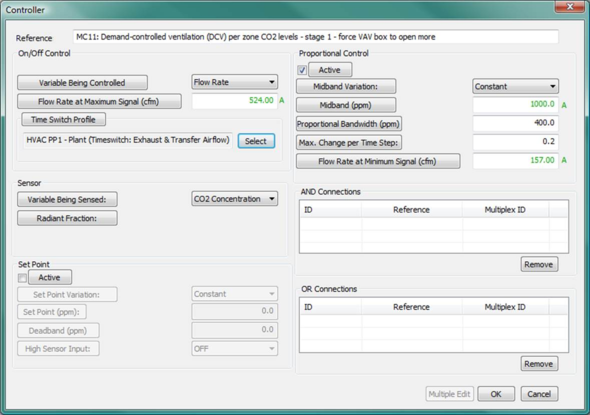
The first stage resembles the proportional controller for VAV zone cooling airflow in terms of min and max airflow, but uses the CO2 level in the room as the sensed value and CO2 setpoint minus 200 ppm (a default that can be overridden) as its midband.
The second stage is modeled as a second outside air damper providing a bypass of sorts around the main OA/economizer damper. This is, as in the single-stage DCV control. All zones with DCV sensors enabled will “vote” on the position of second damper for additional ventilation air. Whichever zones votes for the most open damper position wins the vote. The reason this uses a separate damper set is, once again, to allow the controlled variable to be a target leaving air temperature for the economizer operation and a damper opening percentage (for air from the left branch) for the DCV control. The two dampers are, in effect, one damper with two overlapping modes and means of control.
If desired, a lesser maximum OA percentage can be entered either in the Loads Data spreadsheet for the system, and then applied with an update of other linked controllers, or simply edited in the Percentage flow at Max Signal field within controller MC12: Demand-controlled ventilation (DCV) per zone CO2 levels - stage 2 - demand more system OA.
-
CO
2 sensors – single stage control for dedicated 100% outside air systems (DOAS): For these systems, there is no recirculation path at the system level and thus the air handler is always delivering 100% outside air to the conditioned zones. Therefore, for this fundamental category of system configuration the sensed zone CO
2 level is simply used to directly control the system airflow to just that zone. If the air handler is delivering only tempered air having a relatively neutral temperature to the zones, it may be acceptable for the system airflow to modulate to zero so long as this does not cause CO
2 levels to rise above the ppm setpoint. The default calculations in the Loads Data spreadsheet set the lower bound at 30% of the maximum airflow, however, this can be easily overridden by setting the Flow rate at Minimum Signal in controller MC3 to an alternate value, including zero. When this type of DCV is set up to modulate all the way to zero airflow, the zone damper will normally begin to open again as the CO
2 levels approach the ppm setpoint. The default proportional control bandwidth of 400 ppm, which can also be readily overridden in the controller (MC3 for any system type 09), causes the damper to begin to open at 200 ppm below the setpoint and to reach fully open at 200 ppm above the setpoint.
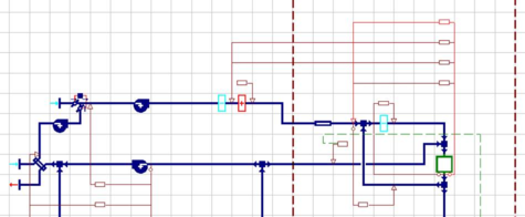
Adding CO2-based demand-controlled ventilation to a multi-zone system
Demand controlled ventilation with zone CO2 sensors can be included in any system. To add zone-CO2 based DCV to multi-zone system that does not have these controls (see components and controls highlighted in the screen captures on subsequent pages), the appropriate source file or example to work from depends upon whether your proposed system will have a dedicated outside air handler or DOAS without recirculation (e.g., prototype systems in the 09 category [at left in the image below]) or will include a recirculation path (e.g., prototype systems in the 05–08 categories[at right in the image below]).


A typical overall room CO2 setpoint might, for example, be in the range of 1,000 ppm, depending upon the application, codes, etc. A single stage control for spaces served by a dedicated outside air system without recirculation (e.g., one of the 09 prototype systems) would simply use this value as the midband to ramp zone ventilation air between minimum and maximum values in keeping with CO2 levels for that zone. A two-stage control for VAV system configurations 05 and 07 (with recirculation) might force the zone VAV box all the way open using a ramp with midband of 900 ppm and then have a second stage ramp with midband of 1,100 ppm used to gradually demand more system OA if the zone CO2 levels continue to rise.
Adding zone-CO2 based DCV to prototype systems in the 09 category is, where applicable, a matter of enabling variable flow for the ventilation air to the zone. This is accomplished by simply setting Flow at Min Signal to a value that is less than Flow at Max Signal. This control (MC3) is pre-defined for all category 09 prototype systems other than active chilled and 4-pipe beams (induction units). In those with “DCV” in the name, the default inputs before autosizing illustrate typical control of ventilation between min and max values (see screen captures below). For those without “DCV” in the name, the default inputs before autosizing provide constant-volume ventilation flow rate (flow at min signal = flow at max signal), thus negating the influence of the CO2 sensor until the flow rates are revised to distinct high and low values.
Specific instructions for category 09 active chilled beam and 4-pipe active beam systems, as well as other prototype system categories, follow below.
For the active chilled beam and 4-pipe active beam systems, the MC3 controller with CO2 sensor is replaced by MC10: Primary airflow to active beam, which modulates primary airflow according to a zone temperature. Because there is also supply air temperature reset—effectively a water flow control valve—on the cooling coil (and heating coil for 4-pipe beams), the MC3 controller with CO2 sensor used on other category 09 systems can be used with these systems without losing space conditioning control.
-
If the DCV airflow is to replace the thermostat-based control of primary airflow to the beam, the setting and reference name within MC10 should be revised to match those of MC3 in any category 09 prototype system with DCV in the name. One means of accomplishing this is to delete MC10, import one of the systems with DCV, and copy the MC3 controller. In any case, if you wish to have the controller pick up the DCV inputs from the Loads Data spreadsheet during autosizing, it is essential that the reference name of the controller begin with “MC3:”, including the colon.
-
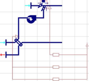
If the DCV is to be added as a secondary means of modulating the airflow to the active beam, the MC3 controller should be manually added as shown in the illustration and dialog below. Again, if you wish to have the controller pick up the DCV inputs from the System Parameters dialog and the Loads Data spreadsheet during autosizing, it is essential that the reference name of the controller begin with “MC3:”, including the colon. Also, the HVAC PP2 or similar user-defined time-switch profile is needed to ensure that the ventilation air does not get stuck on at the minimum flow rate when the building is unoccupied and the ventilation is meant to be off.

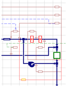
To add zone-CO2 based DCV to systems in categories 05–08, begin by importing system “05b IDDE VAVr - CO2-DCV…” from the HVAC library into your file. Copy the additional damper set and two multiplexed zone-level controllers (MC11 and MC12) from that system to the system to which you would like to apply DCV, as described below.
Figure 1 - 9 : Two-stage DCV components in prototype system 5b are highlighted in this screen capture.
To add zone-CO2 based DCV to multi-zone VAV system 5 or 7 configurations (including most variants):
1. Delete the three connectors marked with a red “X” in step in the image above and move the SA fan, OA/economizer damper, and associated controls one cell to the right.
2. Select and copy the junction, connectors, damper set, and both MC11 and MC12 controllers (pointing to primary airflow path and DCV damper, respectively) as highlighted an placed in step ‚ above. This will provide two-stage DCV-based control that first forces the zone VAV box more open and then (when the VAV box is fully open) demands more system OA at the air handler, consistent with the descriptive Reference names for controllers MC 11 and MC12.
3. Because systems 5 & 7 share the same fundamental configuration as system 5b, the MC11 and MC12 controllers copied from that system to any derivative of either 5 or 7 will remain linked to the “Sys 5,7” tab in the Loads Data spreadsheet. When data is assigned from the spreadsheet to the controllers in the system, they will pick up min and max VAV airflows and CO2 midbands bracketing the target CO2 level set in the System Parameters dialog.
To add zone-CO2 based DCV to multi-zone VAV + fan-powered boxes system 6 or 8 configurations:
1. Delete the three connectors marked with a red “X” in step in the image above and move the SA fan, OA/economizer damper, and associated controls one cell to the right.
2. Select and copy the junction, connectors, damper set, and just the MC12 controller (the controller pointing to the DCV damper) as shown in step ‚ above. This step will provide the DCV-based system OA control, consistent with the labeling of MC12, “Demand-controlled ventilation (DCV) per zone CO2 levels - stage 2 - demand more system OA”
3. To include the initial stage of DCV control that first forces the zone VAV box to open further (until fully open) before demanding additional outside air at the system air-handler, you will also need the MC11 controller; however, because there is loop with fan for the zone fan-powered box in systems 6 and 8, this control needs to occupy a different location on the canvas.
4.
Version 6.5 will include stretchable controller leads for the controlled and sensed nodes, which allows for copying the MC11 controller from system 5b and stretching lead to fit it as shown (figure at right). In releases prior to v6.5, however, the MC11 controller needs to be re-created so as to include the same sensed and controlled variables, etc. as in system 5b. Place the new controller as shown above so that it senses room/zone temperature and controls airflow at the same nodes as the primary airflow VAV control, but without falling on top of the loop for the fan-powered box.
5. Use the dialog for system 5b (shown above) as an example for appropriate sensed and controlled variables, CO2 midband, flow rates, and time switch profile.
a) The sensed variable is CO2 Concentration
b) The controlled variable is Flow Rate
c) Proportional control bandwidth should indicate the range of sensed CO2 concentration (ppm) over which the VAV damper for primary airflow will modulate in response to zone-level CO2. As the zone CO2 rises, this control will be voting on the VAV damper position along with the VAV cooling airflow controller (the highest value at any time step will prevail). To facilitate straightforward coordination of control midbands, set this bandwidth to the same value as used in MC12 (e.g., 400 ppm).
d) The proportional control midband sets the midpoint of the range of sensed CO2 concentration (ppm) over which the VAV damper for primary airflow will modulate in response to zone-level CO2. If this control is to take effect prior to MC12, fully opening the VAV box prior to requesting additional outside air at the system level, and assuming the bandwidths for MC 11 and MC 12 are the same, this midband should be set to one bandwidth less than the midband for MC12. The two proportional bands will then be immediately adjacent, but not overlapping with respect to the sensed value for zone CO2 concentration.
e) Flow Rate at Max Signal and Flow Rate at Min Signal in MC11 should match the values in MC3: Zone VAV cooling airflow control with night-cycle on when set-up temp is exceeded for all multiplex layers. For autosized systems, these values can be copied as a column of numbers from the system Loads Data spreadsheet to the tabular edit or “Data table” view of input fields within the controller dialog (see Chapter 6 for description of multiplex editing).
f) If a non-zero airflow rate is used for the Flow Rate at Min Signal value, as in the autosized controllers, then the time switch profile should be HVAC PP1 or an equivalent profile that will force the minimum flow rate on only when the system airflow is required for space ventilation. This will set the timing the same as any exhaust and/or transfer airflow controls.
g) To disable or enable DCV control (stage 1 and/or stage 2) for any given set of layers, select those layers in the Multiplex Edit dialog while in Global Edit mode and then set the Time Switch Profile in the controllers to either OFF continuously or HVAC PP1 (or user equivalent).
6. Because there are no pre-defined systems in categories 6 and 8 with DCV, there is also no shortcut to the DCV inputs provided for these system configurations within the System Parameters dialog. Parameters related to DCV for these systems should be edited as described above.
The two-stage MC11 and MC12 controls are used only for multi-zone systems with a recirculation path; the DOAS systems have a single-stage control on the ventilation air at the zone level.
The MC13 controller is used only on the prototype 07b Mixed-Mode system wherein it forces the mechanical ventilation to override the natural ventilation when the latter is insufficient to maintain the CO2 levels below the setpoint (subject to a deadband on the order of 200 ppm). This controller could also be copied to another mixed-mode configuration and would be similarly autosized so long as this is based upon a category 05 or 07 configuration.
Airside economizer controls
There are at least three main types of airside economizer control:
· Damper position modulation according to target mixed-air temperature with outside air dry-bulb temperature high limit.
· Damper position modulation according to target mixed-air temperature with outside air dew-point temperature high limit.
· Damper position modulation according to the relative difference in enthalpy between the return and outside air.
On systems with energy recovery, the high-limit sensor for the OA damper is placed downstream of the energy recovery component so that recovery of “coolth” (using the ER device to remove heat from incoming OA when the exiting EA is cooler than the OA and the zones are, on average, in cooling mode) can be allowed to extend the number of OA economizer hours. See the section above regarding controls for the Energy Recover device and bypass damper to understand how this is operated and changes from heat recovery to “coolth” recovery in relation to the system return air temperature.
The pre-defined standard and ASHRAE Baseline HVAC systems modulate the economizer damper position according to a target mixed-air temperature and include an outside air dry-bulb temperature high limit.
Many of the standard pre-defined HVAC systems also include an outdoor dew-point temperature high limit controller (coupled to the DBT high limit control by a logical OR connection); however, this additional controller has an excessively high default DPT high limit that effectively disables it. To enable the DPT high limit, simply change the Set Point input to an appropriate value, such as 55°F or similar.
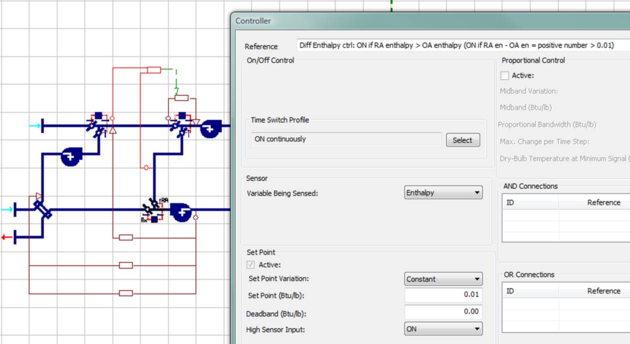
The image above shows an example of a differential enthalpy control for the OA economizer damper. In this example the differential enthalpy control is used as a limiting device with a logical AND connection to the standard dry-bulb high-limit economizer control with mixed-air target temperature. If the dry-bulb high limit is not to be used, either set the high limit to an exceptionally high value (effectively no limit) or replace the standard controller with a simply time switch that set the target temperature for the OC economizer modulation. Light the dry-bulb high-limit control, the differential enthalpy control coupled by a logical AND connection will simply force the OA damper to its minimum OA setting whenever the OA enthalpy is greater than the return-air enthalpy. When the either sensible heat or enthalpy recovery is enabled via the heat exchanger in the lower left corner of the system, the comparison is between the OA enthalpy after this heat exchanger and that of the return air. This example is from the library HVAC system “5c VAV hotel/dorm public areas plus PTAC rooms,” and can be copied from that system.
Return air damper component
This component has a special relationship with the outside air (OA) damper: when located immediately below the OA damper, as in the pre-defined systems, it can force the OA damper to open more than its minimum setting or its current position (when modulating) if needed to provide adequate makeup air for exhausted zones, etc. This should not be seen as a substitute for appropriate minimum setting in the OA damper component. It is mainly intended for systems with variable exhaust flows, such as a laboratory with VAV fume hoods, wherein the variable exhaust flow rate does not exceed the primary supply flow, but does sometimes exceed the OA flow rate as otherwise determined for ventilation and/or economizer operation. This allows for modeling of diversity in exhaust schedules—e.g., simulating relatively random operation of VAV fume hood—so long as they are not in conflict (with respect to On/Off times) with the OA damper control or primary airflow controls that will determine the volume of air flowing to the zones having variable exhaust (even when indirectly supplied via transfer flows from adjacent zones).
Supply fan
The following are the default inputs for the SA Fan components in the standard multi-zone systems within the HVAC library. This is meant to be representative of a typical variable-speed fan (i.e., with variable-frequency or variable-speed drive) in a VAV system. While this will scale with autosizing, the pressure and efficiency performance curves will obviously remain unchanged. For accurate modeling of fan power, users need to enter data for the actual fan they intend to use in the proposed design.
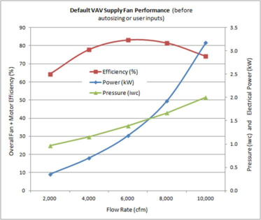
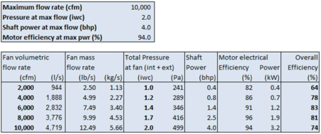
The bold values for flow rate, which is autosizable, total pressure, and overall efficiency are the default values within the supply fan component dialog for multi-zone VAV systems in the HVAC library. The fan performance curve is defined by the series of shaft power (bhp) values relative to the Design shaft power at max flow. The default RA fans use the same curves, but with 1.0 iwc default pressure at maximum flow rate. Default fans for EA, fan-coil units, and fan-powered boxes are assumed to be constant-volume with autosizable flow rate, 0.5 iwc pressure, and 70% overall efficiency. All fans have a default oversizing factor of 1.15 for the flow-rate scaling of the performance curves during autosizing. Note that these fans are notably more efficient than the required defaults for PRM Baseline systems.
Fan performance data in all ASHRAE 90.1 PRM Baseline systems is specific to the required fan power allowances: Pressure and overall efficiency in the SA fan yield the required curve for variable-volume systems and in all Baseline system the SA fan power accounts for all SA + RA + EA fans (but not fans in parallel FPBs). The SA fans have flat pressure and very low efficiencies; RA and EA fans have zero pressure.
Minimum flow controls for night-cycle and unoccupied-hours fan operation
For variable-flow systems, the minimum flow rate during unoccupied hours is set by the autosizing process at the zone level in keeping with the maximum design flow rate for each zone. For example, if the default value of 20% minimum flow is used for supply and return fans, then when any one zone requires minimum flow to maintain a setback temperature via night-cycle fan operation during unoccupied hours, all other zones on the same system will be forced to accept 20% of their max design flow rate. In version 6.5, the default 20% value for minimum fan flow rate can be modified either via the System Parameters dialog or within the Loads Data spreadsheet prior to assigning values from the spreadsheet to controls.
IMPORTATN NOTE: Because the Min Flow value for night-cycle fan flow to any particular zone are written to the MC4: Zone VAV Min airflow when any other zone demands flow in unocc hours controller, manual editing of flow rates in either MC3 or MC4 should be accompanied by corresponding edits to the min fan flow rate values in to values the Zone VAV Min airflow… controller. This is particularly important whenever editing controller values that have not been autosized on layers that were added after autosizing of controls on the previous set of multiplex layers. The reason for this is that it is normal for newly added multiplex layers to pick up all controller inputs and settings from the last layer on the list in the Edit Multiplex dialog. This includes the Zone VAV Min airflow… controller. If any of the manually edited flow rates in MC3 and MC4 VAV airflow controllers are intended to be less than the autosized min flow for the last autosized layer prior to adding more multiplex layers, manual edits to MC3 and MC4 must be accompanied by manual edits to the duplicate MC4 Zone VAV Min airflow… controller. If not, inappropriately high minimum flow rates copied from the previously autosized layer will persist.
Return fan
Cooling coil – system level or AHU
Heating coil – system level or AHU
Duct heat gain/loss component – zone level
Reheat coil and controller (or similar components) – zone level
Zone or “principal room” component
Return air plenum component
 VAV airflow controls
Profiles for proportional control midbands
• Timed variation of values provides nighttime set-back/set-up.
Using a constant static pressure in each row of the fan component dialog, as we do by default, achieves this for a system wherein the fan speed will always be re-set so as maintain the specified static pressure after any downstream adjustment of VAV airflows. This is typical of a a system wherein fan speed is adjusted to maintain a static pressure set point. If the specified static pressure to be maintained by adjusting fan speed is to differ according to fan speed—some fans operate more efficiently or effectively with a particular pressure and speed relationship—then different static pressure numbers can be entered on the rows corresponding to the appropriate fan speed ranges in the fan dialog.
IMPORTATN NOTE: Because the Min Flow value for night-cycle fan flow to any particular zone are written to the MC4: Zone VAV Min airflow when any other zone demands flow in unocc hours controller, manual editing of flow rates in either MC3 or MC4 should be accompanied by corresponding edits to the min fan flow rate values in to values the Zone VAV Min airflow… controller. This is particularly important whenever editing controller values that have not been autosized on layers that were added after autosizing of controls on the previous set of multiplex layers. The reason for this is that it is normal for newly added multiplex layers to pick up all controller inputs and settings from the last layer on the list in the Edit Multiplex dialog. This includes the Zone VAV Min airflow… controller. If any of the manually edited flow rates in MC3 and MC4 VAV airflow controllers are intended to be less than the autosized min flow for the last autosized layer prior to adding more multiplex layers, manual edits to MC3 and MC4 must be accompanied by manual edits to the duplicate MC4 Zone VAV Min airflow… controller. If not, inappropriately high minimum flow rates copied from the previously autosized layer will persist.
Exhaust fan
Exhaust airflow controller
Transfer airflow controller