Parabolic Trough Collector
A parabolic trough collector (PTC) is a line-focus collector which can rotate about a fixed horizontal axis to track the movement of the sun.
A PTC uses a mirror in the shape of a parabolic cylinder to reflect and concentrate solar radiation onto a receiver tube lying along the focal line of the parabolic cylinder. The receiver absorbs the incoming radiation and transforms it into thermal energy which is collected by a fluid medium circulating within the receiver tube. This method can be used either for thermal energy collection, for generating electricity or for both.
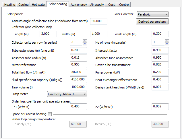
Azimuth angle of collector tube (˚clockwise from north)
Enter the azimuth angle of collector tube
Reflector (one collector unit):
Enter the dimensions of the reflector unit – collector unit length (m), reflector width (m) and reflector focal length (m).
Collector units per row (in series)
Enter the number of number of collector units in each serially-connected collector row (maximum number: 20)
No of rows (in parallel)
Enter the number of rows configured in parallel (maximum number: 20)
Tube extensions (m) (one unit)
Enter the outer radius of absorber tube (note: the cover tube radius is not required)
Intercept factor
The fraction of the beam radiation passing through the collector aperture, which is intercepted by the receiver - defined on the basis, that the mirror is a perfect reflector (and thus a purely geometric parameter).
Absorber tube radius (m)
Enter the outer radius of absorber tube for normal incidence radiation. (note: the cover tube radius is not required)
Absorber tube absorptance
Enter the absorber tube absorptance for normal incidence radiation
Mirror reflectance
Enter the mirror reflectance for the normal incidence radiation; here ‘normal incidence radiation’ means radiation which passes through the aperture plane at normal incidence (but strikes the other surfaces at a variety of angles).
Cover tube transmittance
Enter the absorber tube transmittance for normal incidence radiation
Total fluid flow (l/(h m²))
Enter the total fluid flow rate
Pump power (kW)
Enter pump power. This can be set between 0 and 20 kW (0-50 kW if there is a secondary circulation system) and the default value is 0.2 kW.
Fluid specific heat capacity (J/(kg K))
Enter the specific heat capacity of the fluid
Heat exchanger effectiveness
Enter the heat exchanger effectiveness.
Tank volume (l)
Enter the volume of the tank
Design tank heat loss (kWk/(I day))
Enter the design tank heat loss
Pump
Select the Meter serving the Pump.
Order loss coeffts. per unit aperature area - c1 (W/m²K) c1 (W/m²K²)
Enter the 1st order & 2nd order loss coefficient per unit length
Space or Process
In the case of a collector used for space heating or process load (as opposed to DHW), two more parameters are required. Tick to activate these parameters. The collector cannot be used to feed two different process. If the PTC provides heat for the DHW system, eventual heat excess cannot feed other process (space heating or process load).
Water-loop design temperature - Supply (˚C) Return (˚C)
Enter water-loop design temperature for supply and return loops