Clicking one either of these two icons opens the following window:
Icons
The Pan, Orbit and Zoom functions are controlled by the mouse buttons.
The following icons are available:

Print

Copy image to clipboard

Save: Saves as a .bmp file.

Create avi: You can orbit, zoom and pan in when making your own movie of the model.

Camera Path (See P44 for more information)

X-Ray Effect

Wireframe display

Hidden Line Removal display

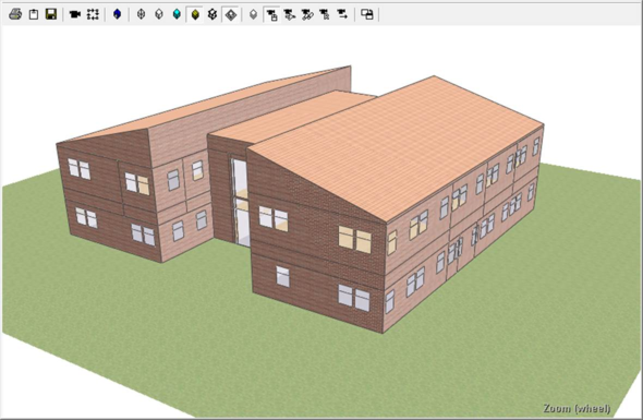
Shaded display

Open Display Settings Dialog

Textured display

Display ground plane.

Mousecam – Standard camera controls.

Flycam – Fly-through camera.

Walkcam – Walk-through camera.

Recover – Reverts views to default.

Goto Space

Toggle between dialog window and docked window
Mousecam controls
|
Control
|
Action
|
Function
|
|
Left mouse button
|
Click and drag
|
Orbit
|
|
Right mouse button
|
Click and drag
|
Pan
|
|
Middle mouse button (wheel)
|
Click and drag
|
Pan
|
|
Middle mouse wheel
|
Scroll
|
Zoom
|
An alternative to scrolling with a middle mouse wheel is to hold the Ctrl button on your keyboard and click and drag the left mouse button to zoom in or out.
Flycam (and Walkcam) controls:
|
Key
|
Function
|
|
W
|
Move forward
|
|
S
|
Move backwards
|
|
A
|
Strafe / sidestep left
|
|
D
|
Strafe / sidestep right
|
|
E
|
Raise eye level
|
|
C
|
Lower eye level
|
Click and drag the left mouse button to look around in Walk-through and Fly-through modes to control direction of motion ( Walk-through movement will be restricted to be parallel to the ground plane).
To speed up scroll the middle mouse wheel forward, scrolling backwards will slow down. Alternatively, press Ctrl and left click drag forwards and backwards to control speed.
Recover will revert all views back to the original defaults when ModelViewer was opened.
The Goto Space feature takes you directly into the space selected in the Model browser. Simply select the space and click on the Goto Space button and the view position will be changed to inside the space.
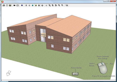
Display Controls Overlay:
In any view the controls can be displayed in the bottom right corner of the Model Viewer by pressing F2.
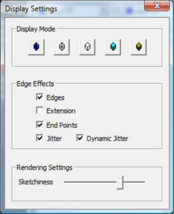
Display Settings
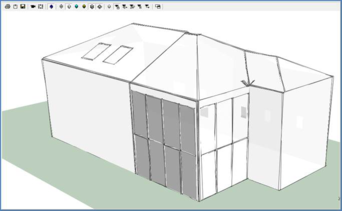
A sketch like style of displaying the model is now available. View settings can be adjusted with the Display Settings dialog. Extension shows architectural extension of lines, end points shows dotted end points and jitter shows sketchy rendering style.
Model viewer shows textures assigned to surfaces in ModelIT. Settings can be changed for improved rendering in the User Preferences dialog. Bump mapping – depth , specular mapping – shininess
By default, controls are displayed each time the Model Viewer is opened. This feature can be switched off in the Model Viewer Settings dialog (Tools > Preferences > Model Viewer Settings tab. For more information please refer to General help topics user guide section 5.7.3.).
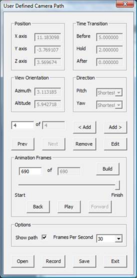
Set Camera Path
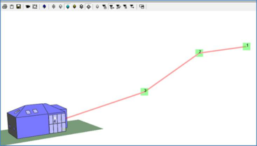
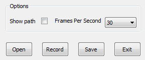
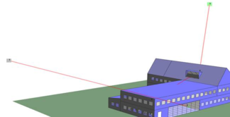
This allows you to record a camera path while moving around the building or even go inside by adding view positions and directions using the Camera Path dialog. These locations can be edited at any time and the camera path will be visualized in model viewer if the option Show path is active. An animation can be created based on the created camera path. (This option can be switched off for final recordings.)
Creating an AVI with the camera path tool
First open up the model viewer, select the Fly through first person camera and click on the camera path tool. Next manoeuvre the camera to the position you would like the AVI to start at.
Now click the right hand Add> arrow to add your first camera position.
Next move your view to the next point where you would like your AVI to stop or change direction and click the Add> button again. Follow this same process to make your full camera path.
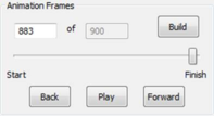
Once you have created your path you click the Build button to create the AVI.
You can then click play to view your AVI, use the Back and Forward to go through the AVI frame by frame or use the fader bar to manually scroll through.
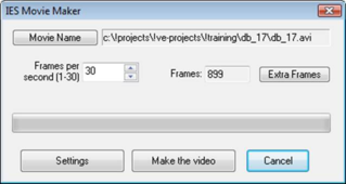
If you are happy with the AVI on the first take then you can click the record button to make your AVI file. Once the software has recorded the camera path you will be given the option of where to save the AVI. Once a suitable location has been selected the Make the video button can be clicked.
Other Options such as the Show path and frames per second can be alter. The camera path can also be saved to be opened and used again at a later date.
When the save option is used a new modelviewer folder is created within the project folder.
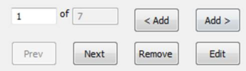
Once you have created your path you have a few options that allow you to edit your camera path.
The Prev and Next buttons can be used to jump to the main camera positions and using the remove option can erase any hold positions.
If you want to <Add a camera into a sequence use the <Add button or if you want to Add> an additional camera hold position onto the end of a sequence then used the Add> button. If you do add or remove any additional cameras remember to perform another build of the AVI.
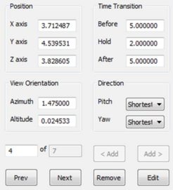
You can also manually edit the camera hold positions, time transitions between points, view orientation and direction. Again use the Prev and Next buttons to cycle through to the position you wish to edit and then click edit.
When you do this you will see the all these options mentioned will no longer be greyed out allowing them to be edited.
These variables can be altered and the steps described on the previous pages followed to create the new AVI and as before the new edited path can be saved for future use.