Calculations
The program can perform day lighting analysis using the point-by-point method.
Analysis can be performed in single-room mode or in multi-room mode (useful if you have many similar rooms).
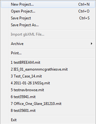
File Menu
The File menu handles file operations. Note that there are no options for opening FlucsDL project files - this is because the FlucsDL project file always has the same name as the ModelIT file but with a *.flp extension. All you need to do is open the correct ModelIT file, and the FlucsDL project file is opened automatically.
Save Project, Save Project As...
These options are the same as in ModelIT, but note that whenever ModelIT saves a model file, it also saves the FlucsDL project file and any other application’s project file.
All other options
These options are the same as in ModelIT.
Exit
Exit the program.
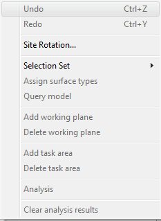
Edit menu
The edit menu handles some of the space properties and the FlucsDL calculations.
Undo
This icon will undo the last change made.
Redo
This icon will redo the last change made.
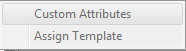
Selection Set
This is only available when one or more rooms are selected. Displays a sub-menu allowing operations on the selected rooms in the model:
Custom Attributes
Displays the Custom attributes dialog box, allowing you to edit the attributes for all the selected rooms.
Assign Template
Displays the Assign template dialog box, allowing you to assign the attributes for all the selected rooms to the values held in a template.
Assign surface types
Allows you to assign surface reflectances and transmittances for the selected surfaces.
Query Model
This is only available when a surface or opening is selected. Shows the property sheet for the selected item in the model. This may be a Surface properties dialog box, or an Opening properties dialogue box, depending on what item was selected.
Add Working Plane
This is only available at body level and Illumination mode in plan view. You will be prompted to enter a point in the plane to be created. When you have done this, the Create working plane dialogue box will be displayed, allowing you to create a named working plane, with an elevation and azimuth, and bounded by the room’s inner surface. This working plane will then be used in subsequent analysis calculations.
Delete Working Plane
This is only available when one or more working planes are selected. Deletes the currently selected working plane.
Add Task Area
This is only available at surface level. You will be prompted to enter all the points defining the task area, and to right-click to finish entering points. When you have done this, the Create task area dialogue box will be displayed, allowing you to create a named task area within the currently selected room surface or working plane. This task area will then be used in subsequent analysis calculations.
Delete Task Area
This is only available when one or more task areas are selected. Deletes the currently selected task area.
Analysis
This is only available when one or more rooms are selected. Displays the Analysis dialogue box to perform the point-by-point analysis calculation. The calculation has two modes:
· Single-room mode – only one room is selected.
· Multi-room mode – more than one room is selected.
Clear Analysis Results
This will clear all the analysis results for the selected rooms.
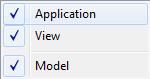
View Menu
The View menu handles display control operations.
Navigator, Browser, Status Bar
These options are the same as in ModelIT.
Toolbars
The Toolbars sub-menu allows you to select which toolbars are displayed.
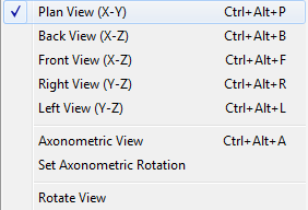
Rotation
The Rotation sub-menu allows you to switch the selected view port between the standard views.
All these options are the same as in ModelIT.
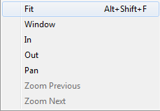
Zoom
The Zoom sub-menu allows you to set the zoom level of the selected view port.
All these options are the same as in ModelIT.
Tabular Space Data
Inactive in this version.
Tabular BTM
Opens the new tabular edit BTM feature.
Tabular air exchanges and internal gains
Inactive in this version.
Flucs Bar
Display or hide the Flucs dialog bar along the bottom of the application.
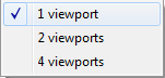
Viewports
The Viewports sub-menu handles the division of the view area into one, two or four viewports.
All these options are the same as in ModelIT.
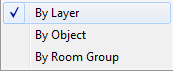
Colour
The Colour sub-menu handles colour settings.
All these options are the same as in ModelIT.
Refresh
As in ModelIT. (Tip: Use the Esc key to abort a slow refresh, e.g. when filled contours are being displayed).
Illuminance
This is available unless in surface mode at body level. Displays the calculated illuminance (lux or fc) on the surfaces.
Luminance
This is available unless in surface mode at body level. Displays luminance (cd/m2 or cd/ft2) derived from the calculated illuminance and the surface reflectances (this option is disabled if daylight factors are being displayed).
What data to display
No Lighting
This is available unless in surface mode at body level. Turns off all the displays of calculated surface lighting levels.
Day Lighting
This is available unless in surface mode at body level. Displays calculated surface day lighting levels.
Daylight Factor
This is available unless in surface mode at body level. Displays calculated surface daylight factors.
Sky view
This is available unless in surface mode at body level. Displays sky view. Sky view is true for any point, when the sky can be seen from that point through any windows and around any obstructions.
How to display data
Contour Levels
This is available unless in surface mode at body level. Displays surface lighting levels using a false colour contour plot.
Filled Contour Levels
This is available unless in surface mode at body level. Displays surface lighting levels using a filled false colour contour plot.
Grey Shading
This is available unless in surface mode at body level. Displays surface lighting levels using a grey scale plot.
Filled Threshold Contour
This is available when illuminance (rather than luminance) is being displayed. It displays the Daylight Threshold dialogue box, which allows you to set a threshold contour for daylight factor above (or below) which the area will be filled and calculated.
Numeric grid point values
This displays the numeric values at each grid point on the surface.
Coloured numeric grid point values
This displays the numeric values at each grid point on the surface, coloured according to contour level.
Threshold Table
This displays a table of threshold values and the area of the room where the threshold is achieved, for each room.
Include 0
This is available unless in surface mode at body level. Toggles on or off whether the scale starts at zero or at the minimum value for all the selected surfaces.
Select colour set
Displays the Select colour set dialogue box, allowing you to choose from a number of different false colour schemes for the contour levels.
Results
Opens the IES HTML Viewer to display the most recently calculated results (Analysis) for the selected room (when below model level) or for all rooms (when at model level).
Save Results
Opens a standard Save As… dialogue box to save the results. The results are stored in HTML format and may be viewed in any web browser. However, only the results for all rooms are stored permanently. Results for individual rooms are only stored temporarily so that they may be displayed during a session. So you may need to use this option if you wish to save the results for all rooms but with a different name or path, or to save the results for an individual room.
Tools Menu
All these options are the same as in ModelIT.
FlucsDL Menu
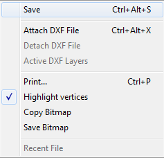
Save
This allows you to save the calculation results to file. Results are saved in any case at the end of a session.
Attach DXF File, Detach DXF File, Active DXF Layers
These options are the same as in ModelIT.
Print...
This option is the same as in ModelIT.
Highlight vertices
Normally all selected rooms will be shown in the view with highlighted vertices, as in other views. If you require vertices to be unhighlighted, to make it easier to view contour levels, remove the tick here.
Copy Bitmap
This copies the current view as a bitmap to the Windows clipboard so that you may paste it into another application, e.g. Paint or Word.
Save Bitmap
This allows you to save the current view as a bitmap (*.BMP) file.
Recent File
This is inactive.
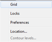
Settings Menu
The Settings menu handles grid and lock settings, and user preferences.
Grid
This option is the same as in ModelIT.
Locks
This option is the same as in ModelIT.
Preferences
This displays the Preferences dialogue box that allows you to change your preference for the style of the Analysis dialogue box and the amount of detail in the results.
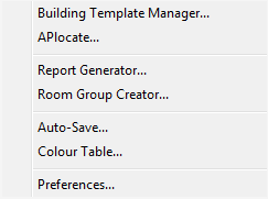
Location
This tool displays the APLocate dialogue box where you can set the building location. The only items of importance for the lighting calculations are the latitude, longitude (required if you will be using the CIE Clear Sky daylight model) and ground reflectance (required if you set a ground plane).
Contour levels...
This displays the Contour levels dialogue box that allows you to override the automatic allocation of contour levels. This is useful if you wish to get screen dumps for absolute comparisons of contour levels.
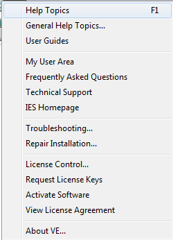
Help Menu
The Help menu gives access to the help information and all the standard licence handling, troubleshooting etc..
Help Topics
Displays this help file.
All other options
All other options are as in ModelIT.