Levels of Decomposition & Display Mode Options
To provide access to different model elements, ModelIT uses a hierarchical approach referred to as levels of decomposition, whereby a model is considered to comprise a series of spaces (optionally grouped into HVAC Zones), and a space comprises a series of surfaces, resulting in three levels of decomposition:
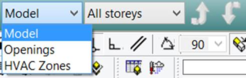
· Model level (display modes Model, Openings, HVAC Zones )
· Space level (display modes Surface, Edit, Component )
· Surface level (display modes Openings, Adjacency )
You can move between decomposition levels using the arrow buttons. Detailed information on modifying the model is provided later in this guide.
When you start ModelIT or open a new project, Display mode is initially set to Model . At this level of decomposition you can create or modify space data, and by either clicking on the canvas or holding the left mouse button down and stretching a rectangle over a portion of the view you can select one or more spaces.
Setting the Display mode to Openings or HVAC Zones presents the same view of the model geometry (the highest level of decomposition).
The Openings display mode allows the selection of openings (doors, windows and holes) in multiple spaces. When working in this mode the Move Down One Level button is inactive.
The HVAC Zones display mode allows the selection of HVAC zones rather than spaces. This mode also renders the Move Down One Level button inactive. Its main application is in ‘thermal’ views such as Apache view. For details consult the ApacheView user guide.
To move down a level of decomposition from Model , first select a single space. The
 Move down one level
 button on the View toolbar is now active. The display changes to fit the selected space into the view window, and the Display mode changes from Model to Surface . The
Display mode drop-down list in the View toolbar now offers the options Surface , Edit , Component .
Surface mode is used to review or modify surface data. Edit mode is used to divide single spaces into multiple composite spaces, to separate composite spaces into individual spaces, and to edit the vertex positions of spaces (see section 6.11 for more details). Component mode is used to place components (previously defined in the CompLib component Modeller) within the model.
In Surface mode you can now move down another level of decomposition to Surface level by using the
 Move Down One Level
 button again.
Display mode changes from Surface to Opening . At this level there are two modes, Openings and Adjacency .
Openings mode is used for creating or modifying windows and doors. Adjacency mode is used to review or modify adjacency data, where an adjacency is an area of a surface which is either adjacent to the exterior or another space.
To move up a level of decomposition use the
 Move Up One Level
 tool button.
Note if you have more than one viewport open, and the level of decomposition in one of the viewports is below Model level, you will not be able to select any other space in any of the other viewports until the level of decomposition is restored to Model in all viewports.
Toolbars
The toolbars save you time by enabling you to select some of the most frequently used commands, without having to select them from the options on the pull-down menu bar at the top of the ModelIT window. Each toolbar is described below from left to right.
Model Toolbar
Colour/Colour table
Layer/Layer properties

Grid Settings

Grid origin

Locks

Draw Arc

Draw Extruded Shape

Draw Prism

Draw Pyramid

Draw Sphere

Draw Hemisphere

Draw Cylinder

Draw Partition

Construction Lines

Remove All Construction Lines

Add Door

Add Window

Add Hole Between Adjacent Spaces

Import gbXML File

Import GEM File

Construct DXF

Create Slice

Model Viewer

APlocate
Edit Toolbar
To activate the edit toolbar first select a space. Refer to section 7 for more information on the edit commands.

Undo

Redo

Select Object

Measure length

Measure angle

Query Coordinates

Copy Selection Set (Click and hold left mouse button to utilise)

Move Selection Set (Click and hold left mouse button to utilise)

Scale Selection Set

Rotate Selection Set

Mirror Selection Set (Click and hold left mouse button to utilise)

Drag Face (works best in axonometric view – when you hover over a face to drag it will highlight in yellow)

Resize Opening
This option activates in edit mode when at a surface level only. When at surface level, select the opening to edit. Then select the vertices of the opening to edit by dragging a window. Click and hold the right mouse button and drag it in the direction to utilise.

Connect Spaces

Edit Attributes

Edit Glazing

Edit Element Heights

Create Roof

Assign Texture

Refresh Display

Delete
Generic View Toolbar
For more information on this toolbar please refer to General help topics user guide section 2.3.4.
Display Mode
The Display mode is selected using a drop-down menu and two arrow buttons on the model toolbar.