|
· Hot water loops
|
· Direct-acting heater/cooler types
|
|
· Generic heat sources
|
· Heating coil
|
|
· Air-to-air heat pump types
|
· Cooling coil
|
|
· Heat transfer loops
|
· Air-to-air heat / enthalpy exchanger
|
|
· Water-to-air heat pump types
|
· Steam humidifier
|
|
· Chilled water loops
|
· Spray chamber / evaporative cooler
|
|
· Generic cooling sources
|
· Fan – left intake
|
|
· Dedicated waterside economizer types
|
· Fan – right intake
|
|
· DX Cooling types
|
· Mixing damper set
|
|
· Unitary cooling system types
|
· Return air damper set
|
|
· Radiator / radiant panel types
|
· Duct heat gain / loss – horizontal
|
|
· Chilled ceiling /radiant panel types
|
· Duct heat gain / loss – vertical
|
|
· Independent time switch controller
|
· Dependent time switch controller
|
· AND connection
|
|
· Independent controller with sensor
|
· Dependent controller with sensor
|
· OR connection
|
|
· Independent differential controller
|
· Dependent differential controller
|
|
Model Workspace
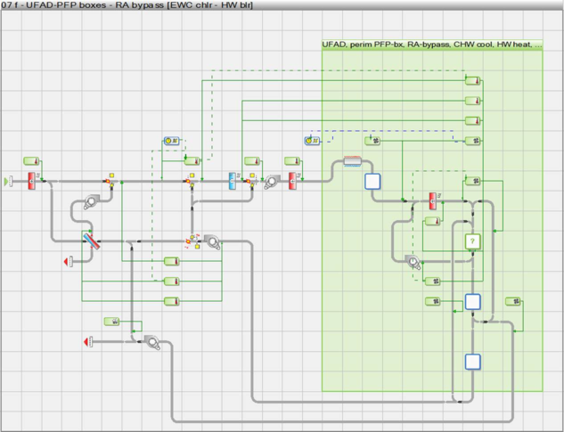
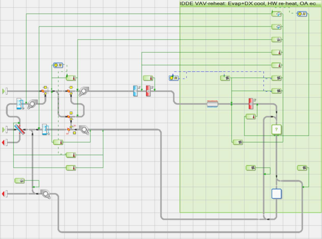
Figure 1 - 1 : The model workspace or canvas displays the HVAC system airside schematic and provides a graphical means of selecting, configuring, organizing, and editing airside component and controller objects. While plant equipment other than that associated with water loops is accessed while remaining in this view, this is what we refer to as the airside HVAC or airside network view.
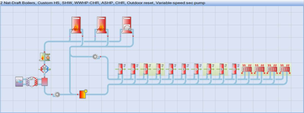
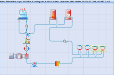
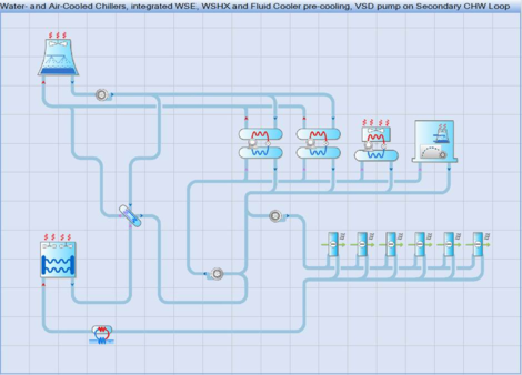
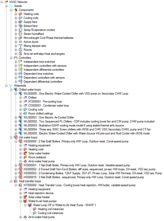
Figure 1 - 2 : There are also three parallel waterside graphic views, as shown above with a range of possible options engaged. These are accessed via the three corresponding toolbar buttons shown below:

Hot water loops

Heat transfer loops

Chilled water loops
These three buttons are toggles that take you back to the airside view when un-clicked.
Component browser

Browser show/hide toolbar button.
Figure 1 - 3 : Component browser tree with HVAC network components and controllers.
The component browser provides a listing of all components in the current ApacheHVAC file. This can be used to locate and/or select a particular type of component or controller within a large or complex HVAC network. Selecting the component or controller within the browser causes it to be highlighted on the network in the model space. The browser can also be useful in determining how many of a particular component or controller type are present.
It is not necessary to hide the component browser for most HVAC system networks, as the speed of this has been significantly improved over earlier versions. When working on exceptionally large or complex HVAC networks, if the opening of component and controller dialogs does begin to slow noticeably, the component browser can be turned OFF by clicking the browser show/hide button on the toolbar. This will further increase the speed with which component and controller dialogs open.
A Component-based Approach to System Simulations
Energy simulation programs have in the past provided models of only certain fixed system types (VAV, induction, fan coils, etc). In practice, building systems do not conform to these rigid system types, and so it was necessary to accept a degree of compromise in the realism of the model.
Figure 1 - 4 : A multi-zone HVAC network—in this case variable-air-volume with indirect-direct evaporative cooling, energy recovery, variation of static pressure with bypass of heat exchangers, duct heat gain, return air plenums, controls for mixed-mode operation with natural ventilation, and primary, transfer, and exhaust airflow paths available to each of the zones in the layered multiplex region.
ApacheHVAC has been designed to impose minimal restrictions on the user in defining the system model. The user is offered a number of basic blocks, each describing a generic type of equipment (heating coil, fan, humidifier, etc.). These basic blocks can be assembled as required to model an actual system configuration, rather than an idealized simplification. The complexity of the model is limited only by the types of block available and some basic rules concerning their interconnection. Within these constraints, it is possible to assemble models of many different system and control configurations and to explore the benefits of variations on standard system types.
An item of plant or control can be described once, and then copied or referenced as many times as may be required to define the system.
HVAC System, Node, and Component results
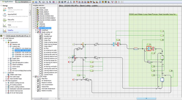
Simulation results for detailed HVAC system modeling in ApacheHVAC can be viewed and analyzed in both Vista and Vista-Pro modules. In addition to the model-level system results and more detailed room-level results, the standard Vista results view offers access to results for airside HVAC network nodes (essentially as shown in VistaPro, below) as well as node-based results for a small number of airside components.
VistaPro provides access to all HVAC results, including those associated with thermal zones (rooms or other spaces in the model), nodes on the airside HVAC network, components on both airside and waterside networks, and all HVAC plant equipment.
Figure 1 - 5 : Selected results for two airside network nodes and a cooling coil component in VistaPro.
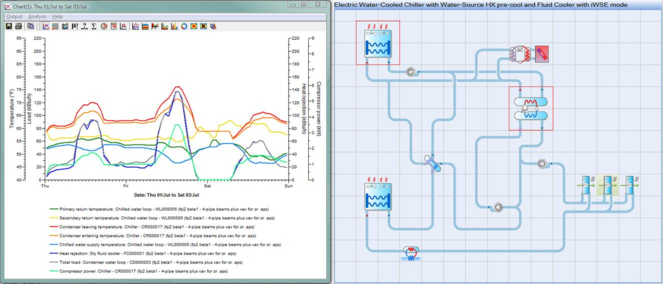
Figure 1 - 6 : Selected results for a chilled water loop, chiller, and fluid cooler in VistaPro.
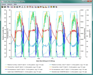
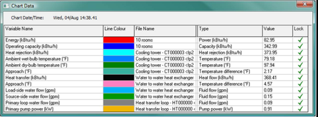
Figure 1 - 7 : Component variables can be locked via the Chart Data dialog (access by clicking the plot area) to include many details on a single plot. Above, energy and operating capacity for ten water-loop heat pumps have been plotted with select performance parameters for the heat exchanger and cooling tower used to reject heat from the heat pumps and the common heat transfer loop that couples them.